DC Motor-Controlled LED Array with Bridge Rectifier
Circuit Documentation
Summary of the Circuit
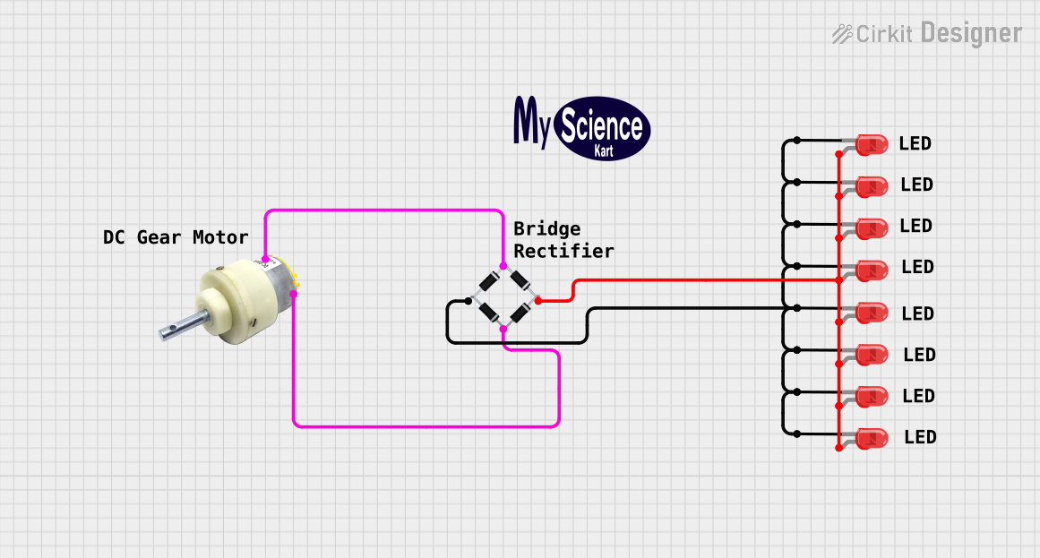
The circuit in question appears to be a simple DC motor control circuit with a bridge rectifier and multiple LEDs used as indicators. The DC gear motor is powered through the bridge rectifier, which likely converts an AC input to a DC output suitable for the motor. The LEDs are connected in parallel across the output of the bridge rectifier, with their anodes tied to the positive output and cathodes to the negative output, indicating the presence of a DC voltage when the motor is powered.
Component List
DC Gear Motor
- Description: A motor that converts DC electrical power into mechanical motion.
- Purpose: To provide mechanical motion for the application.
Bridge Rectifier
- Description: A component that converts alternating current (AC) to direct current (DC).
- Purpose: To supply DC power to the DC gear motor and LEDs.
LEDs: Two Pin (red)
- Description: Light Emitting Diodes that emit red light when forward-biased.
- Purpose: To serve as indicators for the presence of voltage across the bridge rectifier's output.
Comments
- Description: Textual annotations within the circuit design for documentation or explanation purposes.
- Purpose: To provide additional information or clarification within the circuit design.
Logo
- Description: A graphical representation or symbol associated with the circuit or the company.
- Purpose: Branding or identification.
Wiring Details
DC Gear Motor
- Positive: Connected to the positive output of the bridge rectifier (source_in+).
- Negative: Connected to the negative output of the bridge rectifier (Source_in-).
Bridge Rectifier
- Source_in-: Connected to the negative terminal of the DC gear motor.
- source_out-: Connected to the cathodes of all the LEDs.
- source_out+: Connected to the anodes of all the LEDs.
- source_in+: Connected to the positive terminal of the DC gear motor.
LEDs: Two Pin (red)
- Cathode: All cathodes of the LEDs are interconnected and connected to the source_out- of the bridge rectifier.
- Anode: All anodes of the LEDs are interconnected and connected to the source_out+ of the bridge rectifier.
Documented Code
There is no embedded code provided for any microcontrollers in this circuit. Therefore, this section is not applicable to the current documentation.
This documentation provides an overview of the circuit's components and their interconnections. It should be noted that the actual operation and behavior of the circuit would depend on the specific characteristics of the components used and the input power source. Safety considerations, such as current limiting resistors for the LEDs, are not mentioned in the provided information and should be addressed during the actual implementation of the circuit.