
Battery-Powered LED Indicator Circuit with BC547 Transistors
View and Edit Project In Cirkit Designer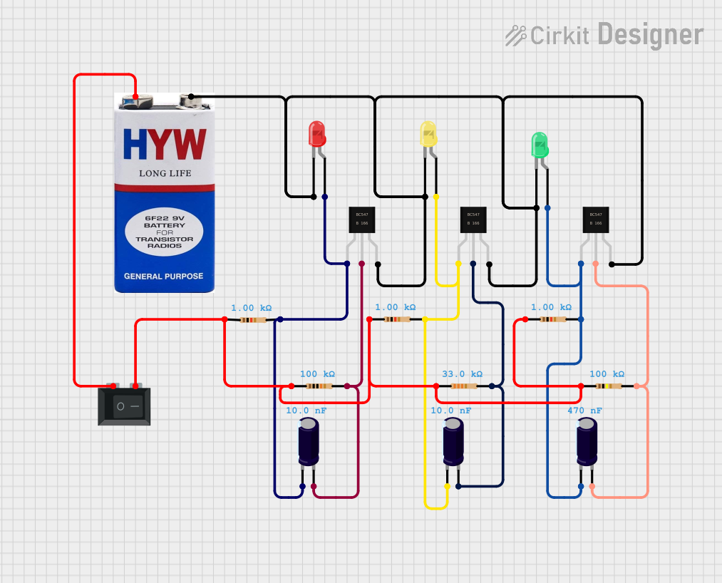
Circuit Documentation
Summary
This document provides a detailed overview of a circuit design that includes various components such as transistors, capacitors, resistors, LEDs, a battery, and a switch. The circuit is designed to demonstrate the interaction between these components, with specific connections and functionalities.
Component List
Transistor (BC547)
- Description: NPN Bipolar Junction Transistor
- Pins: Collector, Base, Emitter
Electrolytic Capacitor
- Description: Capacitor with polarity
- Pins: +, -
- Properties:
- Capacitance: 10 nF (1e-8 Farads)
- Capacitance: 470 nF (4.7e-7 Farads)
Resistor
- Description: Passive electrical component
- Pins: Pin1, Pin2
- Properties:
- Resistance: 100 kΩ (100000 Ohms)
- Resistance: 1 kΩ (1000 Ohms)
- Resistance: 33 kΩ (33000 Ohms)
LED (Red)
- Description: Light Emitting Diode
- Pins: Anode, Cathode
LED (Green)
- Description: Light Emitting Diode
- Pins: Anode, Cathode
LED (Yellow)
- Description: Light Emitting Diode
- Pins: Anode, Cathode
9V Battery
- Description: Power source
- Pins: +, -
Rocker Switch (SPST)
- Description: Single Pole Single Throw Switch
- Pins: 1, 2
Wiring Details
Transistor (BC547)
Emitter:
- Connected to the emitters of other BC547 transistors
- Connected to the cathodes of the green, red, and yellow LEDs
- Connected to the negative terminal of the 9V battery
Collector:
- Connected to the anode of the red LED through a 1 kΩ resistor and a 10 nF capacitor
- Connected to the anode of the yellow LED through a 1 kΩ resistor and a 10 nF capacitor
- Connected to the anode of the green LED through a 1 kΩ resistor and a 470 nF capacitor
Base:
- Connected to the positive terminal of the 10 nF capacitor through a 100 kΩ resistor
- Connected to the positive terminal of the 10 nF capacitor through a 33 kΩ resistor
- Connected to the positive terminal of the 470 nF capacitor through a 100 kΩ resistor
Electrolytic Capacitor
10 nF Capacitor:
- Positive Pin: Connected to the base of a BC547 transistor through a 100 kΩ resistor
- Negative Pin: Connected to the collector of a BC547 transistor and the anode of the red LED through a 1 kΩ resistor
470 nF Capacitor:
- Positive Pin: Connected to the base of a BC547 transistor through a 33 kΩ resistor
- Negative Pin: Connected to the collector of a BC547 transistor and the anode of the green LED through a 1 kΩ resistor
Resistor
100 kΩ Resistor:
- Pin1: Connected to the positive terminal of the 10 nF capacitor
- Pin2: Connected to the base of a BC547 transistor
1 kΩ Resistor:
- Pin1: Connected to the anode of the red LED
- Pin2: Connected to the collector of a BC547 transistor and the negative terminal of the 10 nF capacitor
33 kΩ Resistor:
- Pin1: Connected to the positive terminal of the 470 nF capacitor
- Pin2: Connected to the base of a BC547 transistor
LED (Red)
- Anode: Connected to the collector of a BC547 transistor through a 1 kΩ resistor and a 10 nF capacitor
- Cathode: Connected to the emitters of BC547 transistors and the negative terminal of the 9V battery
LED (Green)
- Anode: Connected to the collector of a BC547 transistor through a 1 kΩ resistor and a 470 nF capacitor
- Cathode: Connected to the emitters of BC547 transistors and the negative terminal of the 9V battery
LED (Yellow)
- Anode: Connected to the collector of a BC547 transistor through a 1 kΩ resistor and a 10 nF capacitor
- Cathode: Connected to the emitters of BC547 transistors and the negative terminal of the 9V battery
9V Battery
- Positive Terminal: Connected to pin 1 of the Rocker Switch (SPST)
- Negative Terminal: Connected to the emitters of BC547 transistors and the cathodes of the LEDs
Rocker Switch (SPST)
- Pin 1: Connected to the positive terminal of the 9V battery
- Pin 2: Connected to pin1 of all resistors
Code
No microcontroller code is provided for this circuit.
This documentation provides a comprehensive overview of the circuit, including a summary, component list, wiring details, and code section. Each component is described in detail, and the wiring connections are clearly outlined to ensure proper assembly and understanding of the circuit.