
Arduino Nano Controlled NRF24L01 Wireless Communication Module
View and Edit Project In Cirkit Designer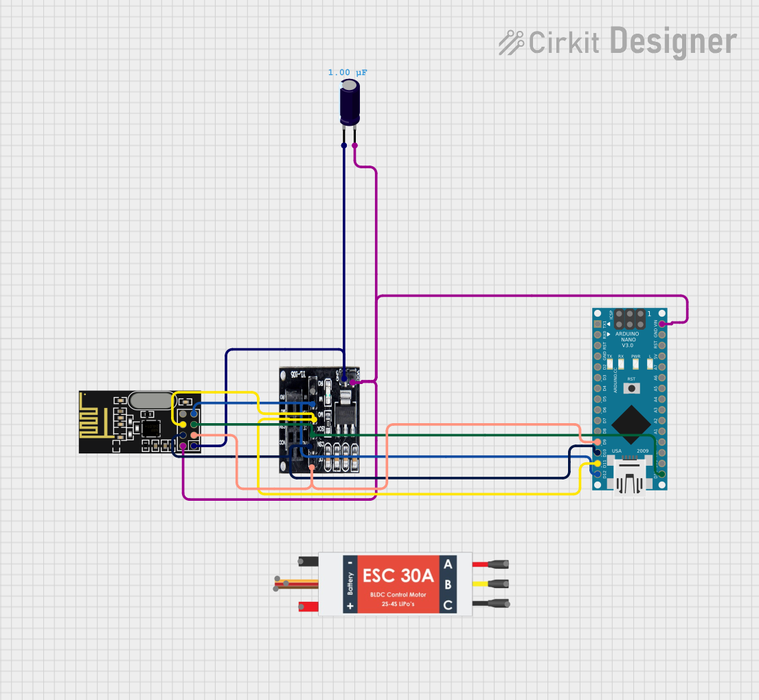
Circuit Documentation
Summary
This document provides a detailed overview of a circuit designed to interface an Arduino Nano with an NRF24L01 module via an NRF24L01 Adapter. The circuit also includes an Electrolytic Capacitor for power supply stabilization and an Electronic Speed Controller (ESC) for motor control, although the ESC is not directly interfaced with the other components in the provided net list.
Component List
Electrolytic Capacitor
- Description: A passive electronic component with an ability to store energy in the form of an electric field.
- Purpose: Used to filter out voltage spikes and smooth the power supply.
- Capacitance: 1 µF (microfarads)
NRF24L01
- Description: A 2.4 GHz wireless transceiver module.
- Purpose: Enables wireless communication between devices.
- Pins: IRQ (not used), MOSI, CSN, VCC (3V), GND, CE, SCK, MISO
NRF24L01 Adapter
- Description: An adapter board for the NRF24L01 module.
- Purpose: Facilitates easy connection and provides voltage regulation for the NRF24L01 module.
- Pins: CE, CSN, SCK, MOSI, MISO, IRQ, VCC, GND
Arduino Nano
- Description: A small, complete, and breadboard-friendly board based on the ATmega328 (Arduino Nano 3.x).
- Purpose: Acts as the main controller for the circuit, interfacing with the NRF24L01 module.
- Pins: D1/TX, D0/RX, RESET, GND, D2, D3, D4, D5, D6, D7, D8, D9, D10, D11/MOSI, D12/MISO, VIN, 5V, A7, A6, A5, A4, A3, A2, A1, A0, AREF, 3V3, D13/SCK
Electronic Speed Controller (ESC)
- Description: An electronic circuit with the purpose to vary an electric motor's speed, its direction, and possibly also to act as a dynamic brake.
- Purpose: Controls the speed of a motor.
- Pins: Battery VCC, Battery GND, Signal, 5v out, GND out, M1, M2, M3
Wiring Details
Electrolytic Capacitor
- Negative Pin (-)
- Connected to GND of NRF24L01 Adapter and NRF24L01
- Positive Pin (+)
- Connected to VCC of NRF24L01 Adapter, NRF24L01, and VIN of Arduino Nano
NRF24L01
- MOSI
- Connected to MOSI of NRF24L01 Adapter and D11/MOSI of Arduino Nano
- CSN
- Connected to CSN of NRF24L01 Adapter and D10 of Arduino Nano
- VCC (3V)
- Connected to VCC of NRF24L01 Adapter and VIN of Arduino Nano
- GND
- Connected to GND of NRF24L01 Adapter and Negative Pin of Electrolytic Capacitor
- CE
- Connected to CE of NRF24L01 Adapter and D9 of Arduino Nano
- SCK
- Connected to SCK of NRF24L01 Adapter and D13/SCK of Arduino Nano
- MISO
- Connected to MISO of NRF24L01 Adapter and D12/MISO of Arduino Nano
NRF24L01 Adapter
- CE, CSN, SCK, MOSI, MISO
- Connected to corresponding pins on NRF24L01 and Arduino Nano
- VCC
- Connected to VIN of Arduino Nano and Positive Pin of Electrolytic Capacitor
- GND
- Connected to Negative Pin of Electrolytic Capacitor
Arduino Nano
- D11/MOSI, D10, D9, D13/SCK, D12/MISO
- Connected to corresponding pins on NRF24L01 and NRF24L01 Adapter
- VIN
- Connected to VCC of NRF24L01 Adapter and Positive Pin of Electrolytic Capacitor
Electronic Speed Controller (ESC)
- Not connected in the provided net list.
Documented Code
Arduino Nano Code (sketch.ino)
void setup() {
  // put your setup code here, to run once:

}

void loop() {
  // put your main code here, to run repeatedly:

}
Additional Notes
- The provided code is a template and does not include specific functionality for the NRF24L01 module or other components.
- Further implementation is required to establish communication and control the connected devices.