Cirkit Designer
Your all-in-one circuit design IDE
Home /
Project Documentation
Arduino UNO Based Heart Rate Monitor with AD8232

Circuit Documentation
Summary of the Circuit
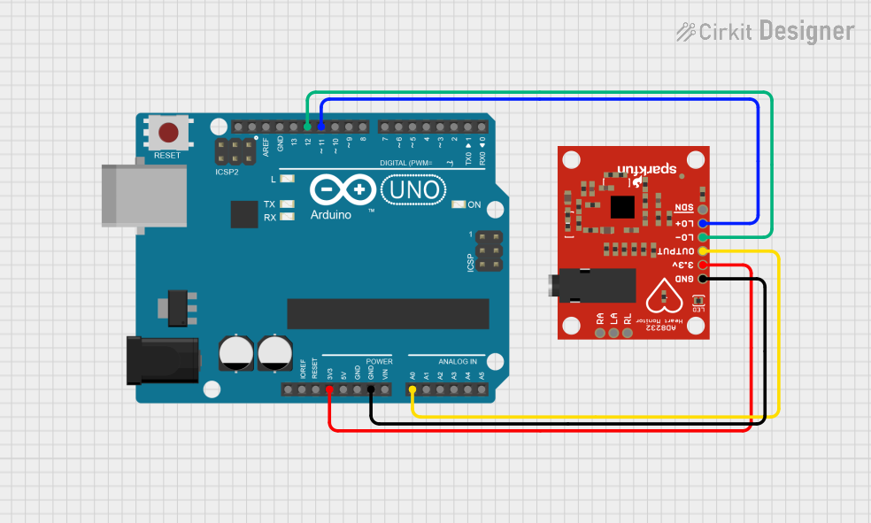
This circuit integrates an Arduino UNO microcontroller with an AD8232 Heart Rate Monitor. The purpose of the circuit is to measure heart rate signals and process them using the Arduino UNO. The AD8232 module outputs the heart rate signal which is then read by the Arduino UNO for further processing.
Component List
Arduino UNO
- Description: A microcontroller board based on the ATmega328P.
- Purpose: Acts as the central processing unit for the circuit, reading sensor data and executing embedded code.
- Pins: UNUSED, IOREF, Reset, 3.3V, 5V, GND, Vin, A0-A5, SCL, SDA, AREF, D0-D13.
AD8232 Heart Rate Monitor
- Description: A single-lead heart rate monitor analog front-end.
- Purpose: Measures electrical activity of the heart and outputs an analog signal.
- Pins: GND, 3.3v, OUTPUT, LO-, LO+, SDN, RA, LA, RL.
Wiring Details
Arduino UNO
- 3.3V connected to AD8232 Heart Rate Monitor 3.3v.
- GND connected to AD8232 Heart Rate Monitor GND.
- A0 connected to AD8232 Heart Rate Monitor OUTPUT.
- D11 connected to AD8232 Heart Rate Monitor LO+.
- D12 connected to AD8232 Heart Rate Monitor LO-.
AD8232 Heart Rate Monitor
- 3.3v connected to Arduino UNO 3.3V.
- GND connected to Arduino UNO GND.
- OUTPUT connected to Arduino UNO A0.
- LO- connected to Arduino UNO D12.
- LO+ connected to Arduino UNO D11.
Documented Code
Arduino UNO Code (sketch.ino)
void setup() {
  // put your setup code here, to run once:

}

void loop() {
  // put your main code here, to run repeatedly:

}
Additional Notes (documentation.txt)
No additional code documentation provided.
This documentation provides an overview of the circuit components, their purpose, and how they are wired together. The code section includes the initial setup for the Arduino UNO, which will be used to process the heart rate signal from the AD8232 module. Further implementation details should be added to the code to handle the signal processing and any other required functionality.