
Circuit Documentation
Summary
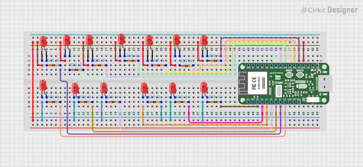
The circuit in question appears to be a series of LED circuits, each with a corresponding resistor, likely for current limiting purposes. These LED-resistor pairs are controlled by a microcontroller, identified as "Glyph C6". The microcontroller has several GPIO pins connected to the resistors, which suggests that it can individually control the LEDs by setting the GPIO pins to a high or low state. The cathodes of all LEDs are connected together and then to the ground (GND) pin of the microcontroller, forming a common ground for all LEDs.
Component List
LEDs
- LED: Two Pin (red): A standard red LED with two pins, anode and cathode. The anode is the positive side, and the cathode is the negative side.
Resistors
- Resistor: A passive two-terminal electrical component that implements electrical resistance as a circuit element. In this circuit, all resistors have a resistance value of 220 Ohms.
Microcontroller
- Glyph C6: A microcontroller unit (MCU) with multiple GPIO pins. It is used to control the state of the LEDs in the circuit.
Wiring Details
LEDs
Each LED has its anode connected to a resistor and its cathode connected to the common ground net.
Resistors
Each resistor is connected in series with an LED. One pin of the resistor is connected to an LED anode, and the other pin is connected to a GPIO pin on the Glyph C6 microcontroller.
Microcontroller (Glyph C6)
The Glyph C6 has its GPIO pins connected to the resistors, allowing it to control the LEDs. The GND pin is connected to the common cathode of all the LEDs.
Documented Code
There is no code provided for the microcontroller in this circuit. The expected behavior would be for the microcontroller to set the GPIO pins to a high state to turn on the LEDs and to a low state to turn them off. Without the code, the specific functionality such as blinking patterns, brightness control, or response to external inputs cannot be documented.
Please note that the actual behavior of the circuit would depend on the code uploaded to the Glyph C6 microcontroller, which is not included in the provided information.