Battery-Powered LED Indicator with Transistor Control
Circuit Documentation
Summary
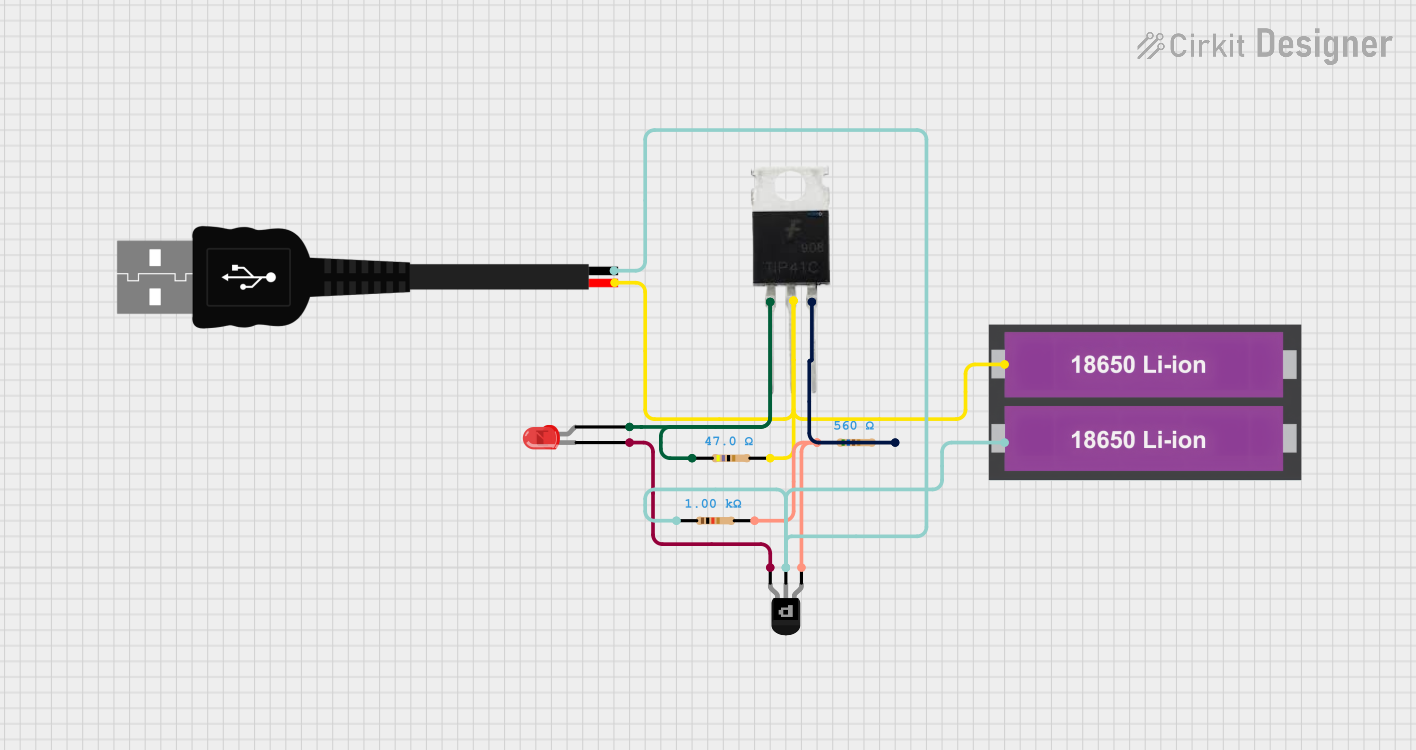
This document provides a detailed overview of a circuit that includes various components such as transistors, resistors, an LED, a USB connection, and a battery pack. The circuit is designed to control the LED using transistors and resistors, powered by a USB connection and a battery pack.
Component List
TIP41C Transistor
- Description: NPN power transistor
- Pins: Base, Collector, Emitter
Resistor (560 Ohms)
- Description: Fixed resistor
- Pins: pin1, pin2
- Properties: Resistance: 560 Ohms
Resistor (47 Ohms)
- Description: Fixed resistor
- Pins: pin1, pin2
- Properties: Resistance: 47 Ohms
PNP Transistor (EBC)
- Description: PNP transistor
- Pins: emitter, base, collector
LED: Two Pin (red)
- Description: Red LED
- Pins: cathode, anode
Resistor (1000 Ohms)
- Description: Fixed resistor
- Pins: pin1, pin2
- Properties: Resistance: 1000 Ohms
USB male 2 pin connection
- Description: USB power connection
- Pins: Negative -, Positive +
18650 Li-ion Battery x 2
- Description: Battery pack
- Pins: +, -
Wiring Details
TIP41C Transistor
Base is connected to:
- pin1 of Resistor (47 Ohms)
- anode of LED: Two Pin (red)
Collector is connected to:
- pin2 of Resistor (47 Ohms)
- Positive + of USB male 2 pin connection
- of 18650 Li-ion Battery x 2
Emitter is connected to:
- pin2 of Resistor (560 Ohms)
Resistor (560 Ohms)
pin1 is connected to:
- pin2 of Resistor (1000 Ohms)
- emitter of PNP Transistor (EBC)
pin2 is connected to:
- Emitter of TIP41C Transistor
Resistor (47 Ohms)
pin1 is connected to:
- Base of TIP41C Transistor
- anode of LED: Two Pin (red)
pin2 is connected to:
- Collector of TIP41C Transistor
- Positive + of USB male 2 pin connection
- of 18650 Li-ion Battery x 2
PNP Transistor (EBC)
emitter is connected to:
- pin2 of Resistor (1000 Ohms)
- pin1 of Resistor (560 Ohms)
base is connected to:
- Negative - of USB male 2 pin connection
- pin1 of Resistor (1000 Ohms)
- of 18650 Li-ion Battery x 2
collector is connected to:
- cathode of LED: Two Pin (red)
LED: Two Pin (red)
anode is connected to:
- pin1 of Resistor (47 Ohms)
- Base of TIP41C Transistor
cathode is connected to:
- collector of PNP Transistor (EBC)
Resistor (1000 Ohms)
pin1 is connected to:
- Negative - of USB male 2 pin connection
- base of PNP Transistor (EBC)
- of 18650 Li-ion Battery x 2
pin2 is connected to:
- pin1 of Resistor (560 Ohms)
- emitter of PNP Transistor (EBC)
USB male 2 pin connection
Positive + is connected to:
- pin2 of Resistor (47 Ohms)
- Collector of TIP41C Transistor
- of 18650 Li-ion Battery x 2
Negative - is connected to:
- pin1 of Resistor (1000 Ohms)
- base of PNP Transistor (EBC)
- of 18650 Li-ion Battery x 2
18650 Li-ion Battery x 2
+ is connected to:
- pin2 of Resistor (47 Ohms)
- Collector of TIP41C Transistor
- Positive + of USB male 2 pin connection
- is connected to:
- pin1 of Resistor (1000 Ohms)
- base of PNP Transistor (EBC)
- Negative - of USB male 2 pin connection
Code
There is no microcontroller code associated with this circuit.