
Arduino and ESP32-Powered Automation System with Sensor Feedback and Actuator Control
View and Edit Project In Cirkit Designer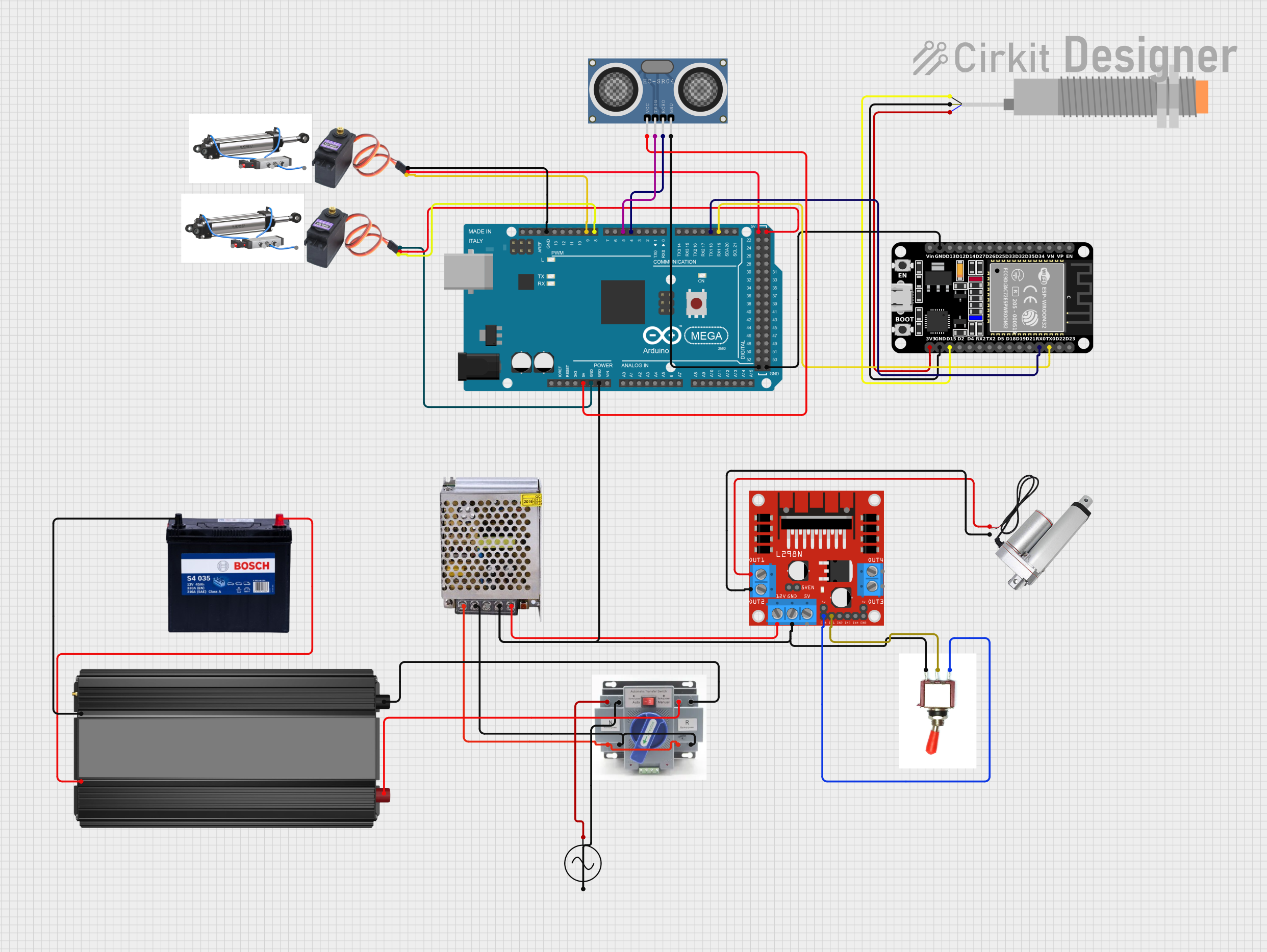
Circuit Documentation
Summary
This document provides a detailed overview of a circuit designed to control a linear actuator, read sensor data, and drive motors. The circuit includes a power supply, motor driver, microcontrollers, sensors, and actuators. The power supply converts AC to DC, providing power to the motor driver and microcontrollers. The Arduino Mega 2560 and ESP32 microcontrollers are used for processing and control. The L298N motor driver controls the linear actuator, and various sensors provide feedback to the microcontrollers. The circuit also includes a battery for power storage and a power inverter for converting DC back to AC.
Component List
- POWER SUPPLY 12V 5AMP: Converts 220V AC to 12V-24V DC, providing power to the circuit.
- ATS (Automatic Transfer Switch): Manages power input sources to ensure continuous power supply.
- L298N DC Motor Driver: Controls the direction and speed of motors.
- MG996R Servo Motor: A high-torque servo motor for precise angular movement.
- Linear Actuator: Converts electrical energy into linear motion.
- Power Inverter: Converts DC power from the battery to AC power.
- Ac Supply: Provides an alternative AC power source.
- 12V 200Ah Battery: Stores electrical energy for backup power.
- ESP32 (30 pin): A microcontroller with Wi-Fi and Bluetooth capabilities for advanced control and communication.
- LJ18A3-H-ZBX Inductive Proximity Sensor: Detects the presence of metallic objects without contact.
- Arduino Mega 2560: A microcontroller board based on the ATmega2560, with numerous I/O pins for interfacing with various components.
- HC-SR04 Ultrasonic Distance Sensor: Measures distances using ultrasonic waves.
- Toggle Switch: A manual switch for controlling the power or logic states within the circuit.
- Pneumatic Cylinder: A device that uses compressed air to produce linear motion.
Wiring Details
POWER SUPPLY 12V 5AMP
- 220V Positive Pole (AC) connected to ATS
- 220V Negative Pole (AC) connected to ATS
- GND (DC) connected to L298N DC motor driver, Toggle Switch, Arduino Mega 2560
- 12V-24V Output (DC) connected to L298N DC motor driver
ATS
- "+" connected to Ac Supply and Power Inverter
- "-" connected to Ac Supply and Power Inverter
L298N DC Motor Driver
- GND connected to Toggle Switch, Arduino Mega 2560
- 12V connected to POWER SUPPLY 12V 5AMP
- OUT1 connected to Linear actuator
- OUT2 connected to Linear actuator
- ENA connected to Toggle Switch
- IN1 connected to Toggle Switch
MG996R Servo Motor (Two Instances)
- GND connected to Arduino Mega 2560
- VCC connected to Arduino Mega 2560
- SIG connected to Arduino Mega 2560 (D8 PWM for one instance, D9 PWM for the other)
Linear Actuator
- "+" connected to L298N DC motor driver (OUT1)
- "-" connected to L298N DC motor driver (OUT2)
Power Inverter
- "+" connected to 12V 200Ah Battery
- "-" connected to 12V 200Ah Battery
Ac Supply
- "+ve" connected to ATS
- "-ve" connected to ATS
12V 200Ah Battery
- 12V connected to Power Inverter
- GND connected to Power Inverter
ESP32 (30 pin)
- GND connected to Arduino Mega 2560
- TX0 connected to Arduino Mega 2560 (D19/RX1)
- RX0 connected to Arduino Mega 2560 (D18/TX1)
LJ18A3-H-ZBX Inductive Proximity Sensor
- SIG (BLK) connected to ESP32 (D15)
- VI (BRN) connected to ESP32 (GND)
- VO (BLU) connected to ESP32 (3V3)
Arduino Mega 2560
- GND connected to L298N DC motor driver, MG996R Servo Motor, HC-SR04 Ultrasonic Distance Sensor, ESP32
- 5V connected to MG996R Servo Motor, HC-SR04 Ultrasonic Distance Sensor
- D8 PWM connected to MG996R Servo Motor (SIG)
- D9 PWM connected to MG996R Servo Motor (SIG)
- D19/RX1 connected to ESP32 (TX0)
- D18/TX1 connected to ESP32 (RX0)
- D4 PWM connected to HC-SR04 Ultrasonic Distance Sensor (ECHO)
- D5 PWM connected to HC-SR04 Ultrasonic Distance Sensor (TRIG)
HC-SR04 Ultrasonic Distance Sensor
- VCC connected to Arduino Mega 2560 (5V)
- ECHO connected to Arduino Mega 2560 (D4 PWM)
- TRIG connected to Arduino Mega 2560 (D5 PWM)
- GND connected to Arduino Mega 2560
Toggle Switch
- Vcc connected to L298N DC motor driver (ENA)
- Sig connected to L298N DC motor driver (IN1)
- Gnd connected to L298N DC motor driver
Documented Code
Arduino Mega 2560 Code (sketch.ino)
void setup() {
  // put your setup code here, to run once:

}

void loop() {
  // put your main code here, to run repeatedly:

}
Note: The provided code for the Arduino Mega 2560 is a template with empty setup and loop functions. This code needs to be populated with the logic to control the connected components based on the requirements of the circuit.
ESP32 Code
No code was provided for the ESP32 microcontroller. It is assumed that the ESP32 will be programmed to handle communication and sensor data processing as per the circuit's design requirements.