Arduino UNO R4 WiFi Controlled Data Logger with BNO055 Sensor and Micro SD Storage
Circuit Documentation
Summary
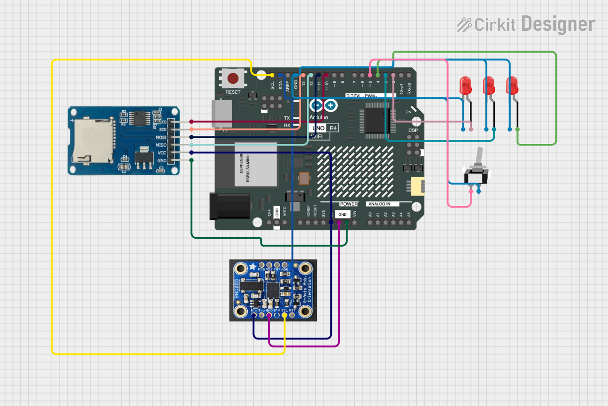
This circuit integrates a microcontroller, a Micro SD Card Module, multiple LEDs, a toggle switch, and a BNO055 sensor. The microcontroller used is an Arduino UNO R4 WiFi, which manages the communication with the Micro SD Card Module and the BNO055 sensor, as well as controlling the LEDs. The Micro SD Card Module is connected via SPI to the Arduino, and the BNO055 sensor is interfaced through I2C. The LEDs are individually controlled by digital pins on the Arduino and are turned on or off based on the logic level at these pins. The toggle switch is used to control the ground connection to the LEDs.
Component List
- Micro SD Card Module: A storage module that allows the microcontroller to read from and write to a micro SD card using SPI communication.
- LED: Two Pin (red): A basic red LED that emits light when a forward current passes through it.
- Toggle Switch SPST: A single-pole single-throw switch that can connect or disconnect the circuit it is part of.
- BNO055: A 9-axis absolute orientation sensor with I2C communication that provides acceleration, orientation, and magnetic field strength data.
- Arduino UNO R4 WiFi: A microcontroller board based on the ATmega328, with integrated WiFi capabilities. It is the central controller of the circuit.
Wiring Details
Micro SD Card Module
- VCC: Connected to the 5V output from the Arduino UNO R4 WiFi.
- GND: Connected to the ground (GND) on the Arduino UNO R4 WiFi.
- CS: Connected to digital pin D10 on the Arduino UNO R4 WiFi.
- MOSI: Connected to digital pin D11 on the Arduino UNO R4 WiFi.
- MISO: Connected to digital pin D12 on the Arduino UNO R4 WiFi.
- SCK: Connected to digital pin D13 on the Arduino UNO R4 WiFi.
LED: Two Pin (red)
- Anode: Each LED anode is connected to a different digital pin (D2, D3, D4) on the Arduino UNO R4 WiFi.
- Cathode: All LED cathodes are connected together and to the common terminal (COM) of the Toggle Switch SPST.
Toggle Switch SPST
- L1: Connected to digital pin D5 on the Arduino UNO R4 WiFi.
- COM: Connected to the cathodes of all the LEDs and to the ground (GND) on the Arduino UNO R4 WiFi.
BNO055
- Vin: Connected to the 5V output from the Arduino UNO R4 WiFi.
- GND: Connected to the ground (GND) on the Arduino UNO R4 WiFi.
- SDA: Connected to the SDA pin on the Arduino UNO R4 WiFi.
- SCL: Connected to the SCL pin on the Arduino UNO R4 WiFi.
Documented Code
Arduino UNO R4 WiFi
sketch.ino
void setup() {
  // put your setup code here, to run once:

}

void loop() {
  // put your main code here, to run repeatedly:

}
documentation.txt
(No additional documentation provided for the code)
This concludes the documentation for the given circuit. The code provided is a template and does not contain any functional logic. It is expected that the user will add the necessary setup and loop code to control the components as per the requirements of their application.