
Arduino UNO-Based Flood Alert System with GSM and LCD Display
View and Edit Project In Cirkit Designer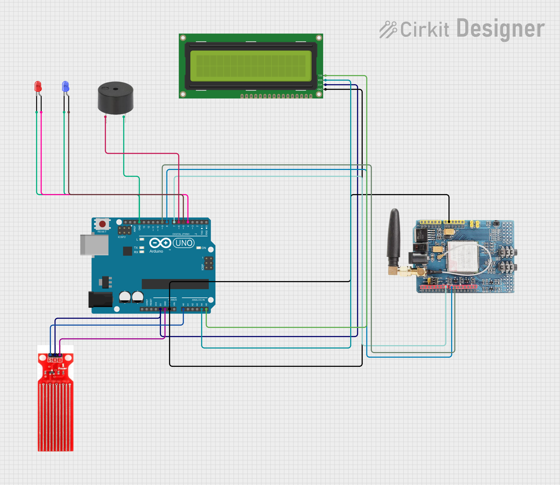
Circuit Documentation
Summary
This circuit is designed to monitor water levels using a water sensor and provide alerts through an LCD display, buzzer, and LEDs. It also has the capability to send SMS alerts and make calls using a GSM module. The core of the circuit is an Arduino UNO microcontroller, which interfaces with various components to achieve the desired functionality.
Component List
Arduino UNO
- Description: Microcontroller board based on the ATmega328P.
- Pins: UNUSED, IOREF, Reset, 3.3V, 5V, GND, Vin, A0, A1, A2, A3, A4, A5, SCL, SDA, AREF, D13, D12, D11, D10, D9, D8, D7, D6, D5, D4, D3, D2, D1, D0
Buzzer
- Description: An audio signaling device.
- Pins: PIN, GND
16x2 I2C LCD
- Description: A 16x2 character LCD display with I2C interface.
- Pins: GND, VCC, SDA, SCL
Water Sensor
- Description: A sensor to detect water levels.
- Pins: Signal, VCC, GND
GSM SIM900
- Description: A GSM module for sending SMS and making calls.
- Pins: A5, A4, A3, A2, A1, A0, 5V, GND, 3.3V, RESET, D0, D1, D2, D3, D4, D5, D6, D7, D8, D9, D10, D11, D12, D13, AREF
LED: Two Pin (red)
- Description: A red LED.
- Pins: cathode, anode
LED: Two Pin (blue)
- Description: A blue LED.
- Pins: cathode, anode
Wiring Details
Arduino UNO
5V connected to:
- Water Sensor (VCC)
- 16x2 I2C LCD (VCC)
GND connected to:
- Water Sensor (GND)
- 16x2 I2C LCD (GND)
- GSM SIM900 (GND)
- LED: Two Pin (blue) (cathode)
- Buzzer (GND)
- LED: Two Pin (red) (cathode)
A0 connected to:
- Water Sensor (Signal)
A4 connected to:
- 16x2 I2C LCD (SDA)
A5 connected to:
- 16x2 I2C LCD (SCL)
D9 connected to:
- GSM SIM900 (D9)
D8 connected to:
- GSM SIM900 (D8)
D7 connected to:
- GSM SIM900 (D7)
D6 connected to:
- Buzzer (PIN)
D5 connected to:
- LED: Two Pin (blue) (anode)
D4 connected to:
- LED: Two Pin (red) (anode)
Buzzer
PIN connected to:
- Arduino UNO (D6)
GND connected to:
- Arduino UNO (GND)
16x2 I2C LCD
GND connected to:
- Arduino UNO (GND)
VCC connected to:
- Arduino UNO (5V)
SDA connected to:
- Arduino UNO (A4)
SCL connected to:
- Arduino UNO (A5)
Water Sensor
Signal connected to:
- Arduino UNO (A0)
VCC connected to:
- Arduino UNO (5V)
GND connected to:
- Arduino UNO (GND)
GSM SIM900
GND connected to:
- Arduino UNO (GND)
D9 connected to:
- Arduino UNO (D9)
D8 connected to:
- Arduino UNO (D8)
D7 connected to:
- Arduino UNO (D7)
LED: Two Pin (red)
cathode connected to:
- Arduino UNO (GND)
anode connected to:
- Arduino UNO (D4)
LED: Two Pin (blue)
cathode connected to:
- Arduino UNO (GND)
anode connected to:
- Arduino UNO (D5)
Documented Code
#include <LiquidCrystal_I2C.h>
#include <SoftwareSerial.h>

// Create software serial object to communicate with SIM900
SoftwareSerial mySerial(7, 8); // SIM900 Tx & Rx connected to Arduino #7 & #8

const int waterSensorPin = A0; // Pin where water level sensor is connected
const int threshold = 500;     // Define a threshold for water level
const int buzzerPin = 6;       // Pin where the buzzer is connected
const int redLedPin = 4;       // Pin where the red LED is connected
const int blueLedPin = 5;      // Pin where the blue LED is connected

// Initialize the LCD with the I2C address (commonly 0x27 or 0x3F)
LiquidCrystal_I2C lcd(0x27, 16, 2); // Adjust the address based on your I2C module

void setup() {
  // Begin serial communication with Arduino and Serial Monitor
  Serial.begin(9600);

  // Begin serial communication with SIM900
  mySerial.begin(9600);

  // Initialize pins as output
  pinMode(buzzerPin, OUTPUT);
  pinMode(redLedPin, OUTPUT);
  pinMode(blueLedPin, OUTPUT);

  // Default state: Blue LED is ON, others OFF
  digitalWrite(buzzerPin, LOW);
  digitalWrite(redLedPin, LOW);
  digitalWrite(blueLedPin, HIGH);

  // Initialize the LCD
  lcd.init();
  lcd.backlight();
  lcd.setCursor(0, 0);
  lcd.print("Initializing...");
  Serial.println("Initializing...");
  delay(1000);

  // Test SIM900 communication
  mySerial.println("AT"); // Handshaking with SIM900
  updateSerial();

  delay(2000); // Small delay to ensure SIM900 is ready
  lcd.clear();
}

void loop() {
  int waterLevel = analogRead(waterSensorPin); // Read water level sensor

  // Send water level as JSON data
  String json = "{\"waterLevel\": " + String(waterLevel) + "}";
  Serial.println(json);  // Send the water level in JSON format

  // Display water level on the LCD
  lcd.setCursor(0, 0);
  lcd.print("Water Level:    "); // Clear line
  lcd.setCursor(12, 0);
  lcd.print(waterLevel); // Display water level

  // Check if water level exceeds the threshold
  if (waterLevel > threshold) {
    String alertJson = "{\"alert\":\"Water level threshold exceeded!.....Flood alert\"}";
    Serial.println(alertJson);  // Send alert message as JSON

    // Activate flood alert indicators
    digitalWrite(buzzerPin, HIGH);
    digitalWrite(redLedPin, HIGH);
    digitalWrite(blueLedPin, LOW);
    lcd.setCursor(0, 1);
    lcd.print("Flood Alert   "); // Display normal status

    // Send SMS alert
    sendSMS("+9779840295109", "Flood Alert: Water level has reached a critical point."); // Replace with actual phone number

    delay(5000); // Wait before making the call

    // Initiate Flood Alert call
    Serial.println("Initiating Flood Alert call...");
    mySerial.println("ATD+9779840295109;"); // Replace with your phone number
    updateSerial();

    delay(20000); // Call for 20 seconds
    mySerial.println("ATH"); // Hang up
    updateSerial();
  } else {
    // Normal state
    String alertJson = "{\"alert\":\"Water level Normal!\"}";
    Serial.println(alertJson);  // Send alert message as JSON
    digitalWrite(buzzerPin, LOW);
    digitalWrite(redLedPin, LOW);
    digitalWrite(blueLedPin, HIGH);

    lcd.setCursor(0, 1);
    lcd.print("Level Normal   "); // Display normal status
  }

  delay(5000); // Wait 5 seconds before next check
}

void sendSMS(String phoneNumber, String message) {
  mySerial.println("AT+CMGF=1"); // Set SMS mode to text
  delay(1000);
  mySerial.println("AT+CMGS=\"" + phoneNumber + "\""); // Specify the phone number
  delay(1000);
  mySerial.println(message); // Send the alert message
  delay(1000);
  mySerial.write(26); // Send Ctrl+Z to send the