
Arduino UNO-Based GPS and GSM Tracking System with Ultrasonic Sensing and OLED Display
View and Edit Project In Cirkit Designer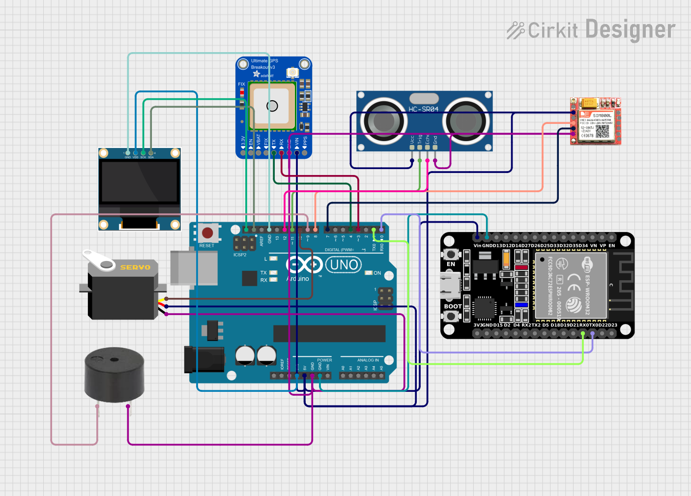
Circuit Documentation
Summary
This circuit integrates various components controlled by an Arduino UNO microcontroller to perform a range of functions. The circuit includes a GPS module for location tracking, a GSM module for cellular communication, an ultrasonic sensor for distance measurement, a servo motor for actuation, an OLED display for user interface, an ESP32 for Wi-Fi/Bluetooth connectivity, and a buzzer for audio feedback. The Arduino UNO serves as the central processing unit, interfacing with each module and sensor to create a multifunctional system.
Component List
Arduino UNO
- Microcontroller board based on the ATmega328P
- It has 14 digital input/output pins, 6 analog inputs, a 16 MHz quartz crystal, a USB connection, a power jack, an ICSP header, and a reset button.
Adafruit Ultimate GPS v3
- A GPS module with 66 channels and a 10 Hz update rate
- It has an onboard patch antenna and a u.FL connector for an external active antenna.
SIM800L
- A GSM/GPRS module that supports quad-band 850/900/1800/1900MHz
- It can be used for SMS, data, and voice communications.
HC-SR04 Ultrasonic Sensor
- An ultrasonic distance sensor capable of measuring distances from 2cm to 400cm
- It operates on a 5V supply and provides echo signals with respect to object distances.
Servo
- A rotary actuator or linear actuator that allows for precise control of angular or linear position, velocity, and acceleration.
0.96" OLED
- A small display module with 128x64 pixels resolution
- It uses the I2C interface for communication.
ESP32 (30 pin)
- A microcontroller with integrated Wi-Fi and dual-mode Bluetooth
- It has a wide range of features including numerous GPIOs, analog inputs, UART, SPI, I2C interfaces, and more.
Buzzer
- An audio signaling device that can be used to create beeps, tones, and alerts.
Wiring Details
Arduino UNO
3.3Vconnected to the OLED display VDD5Vconnected to the ESP32 Vin, GPS VIN, Servo vcc, SIM800L VCC, Ultrasonic Sensor VCCGNDconnected to the buzzer GND, GPS GND, Servo gnd, SIM800L GND, Ultrasonic Sensor GND, OLED GND, and ESP32 GNDSCLconnected to the OLED SCKSDAconnected to the OLED SDAD12connected to the Ultrasonic Sensor ECHOD11connected to the Ultrasonic Sensor TRIGD10connected to the Servo pulseD9connected to the buzzer PIND8connected to the SIM800L RXDD7connected to the SIM800L TXDD4connected to the GPS TXD3connected to the GPS RXD1connected to the ESP32 RX0D0connected to the ESP32 TX0
Adafruit Ultimate GPS v3
VINconnected to Arduino UNO 5VGNDconnected to Arduino UNO GNDTXconnected to Arduino UNO D4RXconnected to Arduino UNO D3
SIM800L
VCCconnected to Arduino UNO 5VGNDconnected to Arduino UNO GNDRXDconnected to Arduino UNO D8TXDconnected to Arduino UNO D7
HC-SR04 Ultrasonic Sensor
VCCconnected to Arduino UNO 5VTRIGconnected to Arduino UNO D11ECHOconnected to Arduino UNO D12GNDconnected to Arduino UNO GND
Servo
vccconnected to Arduino UNO 5Vpulseconnected to Arduino UNO D10gndconnected to Arduino UNO GND
0.96" OLED
VDDconnected to Arduino UNO 3.3VSCKconnected to Arduino UNO SCLSDAconnected to Arduino UNO SDAGNDconnected to Arduino UNO GND
ESP32 (30 pin)
Vinconnected to Arduino UNO 5VGNDconnected to Arduino UNO GNDRX0connected to Arduino UNO D1TX0connected to Arduino UNO D0
Buzzer
PINconnected to Arduino UNO D9GNDconnected to Arduino UNO GND
Documented Code
Arduino UNO Code (sketch.ino)
void setup() {
  // put your setup code here, to run once:

}

void loop() {
  // put your main code here, to run repeatedly:

}
Note: The provided code for the Arduino UNO is a template with empty setup and loop functions. The actual functionality needs to be implemented based on the requirements of the circuit's application.