
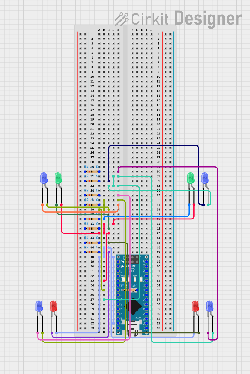
Circuit Documentation
Summary
This circuit involves an Arduino Nano microcontroller controlling multiple LEDs (red, green, and blue) through a series of resistors. The LEDs are connected to various digital pins on the Arduino Nano, and each LED has a corresponding resistor to limit the current.
Component List
Arduino Nano
- Description: A small, complete, and breadboard-friendly board based on the ATmega328P.
- Pins: D1/TX, D0/RX, RESET, GND, D2, D3, D4, D5, D6, D7, D8, D9, D10, D11/MOSI, D12/MISO, VIN, 5V, A7, A6, A5, A4, A3, A2, A1, A0, AREF, 3V3, D13/SCK
Resistor (82 Ohms)
- Description: A resistor with a resistance of 82 Ohms.
- Pins: pin1, pin2
LED: Two Pin (red)
- Description: A red LED with two pins.
- Pins: cathode, anode
LED: Two Pin (green)
- Description: A green LED with two pins.
- Pins: cathode, anode
LED: Two Pin (blue)
- Description: A blue LED with two pins.
- Pins: cathode, anode
Wiring Details
Arduino Nano
- D2
- Connected to the anode of the green LED.
- Connected to the anode of another green LED.
- D4
- Connected to the anode of the blue LED.
- Connected to the anode of another blue LED.
- D6
- Connected to the anode of the blue LED.
- Connected to the anode of another blue LED.
- D11/MOSI
- Connected to the anode of the red LED.
- Connected to the cathode of another red LED.
- A5
- Connected to pin2 of a resistor.
Resistors
- Resistor 1
- pin1: Connected to pin1 of other resistors.
- pin2: Connected to the cathode of a red LED.
- Resistor 2
- pin1: Connected to pin1 of other resistors.
- pin2: Connected to the cathode of another red LED.
- Resistor 3
- pin1: Connected to pin1 of other resistors.
- pin2: Connected to the cathode of a green LED.
- Resistor 4
- pin1: Connected to pin1 of other resistors.
- pin2: Connected to the cathode of another green LED.
- Resistor 5
- pin1: Connected to pin1 of other resistors.
- pin2: Connected to the cathode of a blue LED.
- Resistor 6
- pin1: Connected to pin1 of other resistors.
- pin2: Connected to the cathode of another blue LED.
- Resistor 7
- pin1: Connected to pin1 of other resistors.
- pin2: Connected to the cathode of another blue LED.
- Resistor 8
- pin1: Connected to pin1 of other resistors.
- pin2: Connected to the cathode of another blue LED.
- Resistor 9
- pin1: Connected to pin1 of other resistors.
- pin2: Connected to pin2 of another resistor.
LEDs
- Red LED 1
- anode: Connected to D11/MOSI of the Arduino Nano.
- cathode: Connected to pin2 of a resistor.
- Red LED 2
- anode: Connected to D11/MOSI of the Arduino Nano.
- cathode: Connected to pin2 of another resistor.
- Green LED 1
- anode: Connected to D2 of the Arduino Nano.
- cathode: Connected to pin2 of a resistor.
- Green LED 2
- anode: Connected to D2 of the Arduino Nano.
- cathode: Connected to pin2 of another resistor.
- Blue LED 1
- anode: Connected to D4 of the Arduino Nano.
- cathode: Connected to pin2 of a resistor.
- Blue LED 2
- anode: Connected to D4 of the Arduino Nano.
- cathode: Connected to pin2 of another resistor.
- Blue LED 3
- anode: Connected to D6 of the Arduino Nano.
- cathode: Connected to pin2 of a resistor.
- Blue LED 4
- anode: Connected to D6 of the Arduino Nano.
- cathode: Connected to pin2 of another resistor.
Code Documentation
Arduino Nano Code
void setup() {
  // put your setup code here, to run once:

}

void loop() {
  // put your main code here, to run repeatedly:

}
This code is a basic template for the Arduino Nano. The setup() function is where you initialize your settings, and the loop() function is where you place the main code that runs repeatedly. Currently, both functions are empty and need to be filled with the appropriate logic for controlling the LEDs.