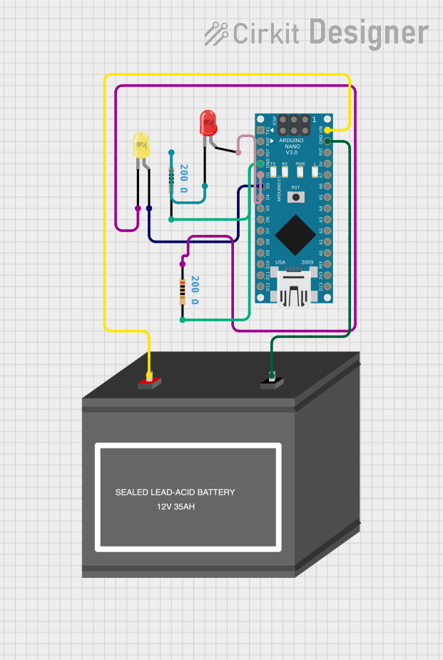
Arduino Nano Controlled Blinking LED Circuit

Circuit Documentation
Summary
This circuit consists of an Arduino Nano microcontroller, two LEDs (one yellow and one red), two resistors, and a 12V battery. The Arduino Nano is powered by the 12V battery and controls the blinking of the two LEDs at different rates. Each LED is connected in series with a resistor to limit the current through the LEDs, protecting them from damage. The Arduino Nano's digital pins D2 and D3 are used to control the LEDs, with D2 connected to the red LED and D3 to the yellow LED.
Component List
Arduino Nano
- Microcontroller with a variety of digital and analog pins.
- It has a built-in USB interface for programming and serial communication.
- Operates at 5V logic level.
LED: Two Pin (yellow)
- A yellow light-emitting diode with an anode and cathode for emitting yellow light when forward-biased.
LED: Two Pin (red)
- A red light-emitting diode with an anode and cathode for emitting red light when forward-biased.
Resistor (200 Ohms)
- Two resistors each with a resistance of 200 Ohms.
- Used to limit the current through the LEDs.
12V Battery (mini)
- A power source providing a voltage of 12V to power the circuit.
Wiring Details
Arduino Nano
- VIN connected to the positive terminal of the 12V battery.
- GND connected to the negative terminal of the 12V battery and the second pin of both resistors.
- D2 connected to the anode of the red LED.
- D3 connected to the anode of the yellow LED.
LED: Two Pin (yellow)
- Anode connected to Arduino Nano's D3.
- Cathode connected to the first pin of one 200 Ohm resistor.
LED: Two Pin (red)
- Anode connected to Arduino Nano's D2.
- Cathode connected to the first pin of the other 200 Ohm resistor.
Resistor (200 Ohms)
- One resistor's first pin connected to the cathode of the yellow LED, and the second pin connected to the Arduino Nano's GND.
- The other resistor's first pin connected to the cathode of the red LED, and the second pin connected to the Arduino Nano's GND.
12V Battery (mini)
- + connected to Arduino Nano's VIN.
- - connected to Arduino Nano's GND.
Documented Code
// Code for controlling the blinking of two LEDs using an Arduino Nano

void setup() {
  pinMode(2, OUTPUT); // Set D2 as an output for the red LED
  pinMode(3, OUTPUT); // Set D3 as an output for the yellow LED
}

void loop() {
  unsigned long currentMillis = millis();
  static unsigned long previousMillisLED1 = 0;
  static unsigned long previousMillisLED2 = 0;
  static bool led1State = LOW;
  static bool led2State = LOW;

  // Blink the red LED every 250 ms
  if (currentMillis - previousMillisLED1 >= 250) {
    previousMillisLED1 = currentMillis;
    led1State = !led1State;
    digitalWrite(2, led1State);
  }

  // Blink the yellow LED every 1000 ms
  if (currentMillis - previousMillisLED2 >= 1000) {
    previousMillisLED2 = currentMillis;
    led2State = !led2State;
    digitalWrite(3, led2State);
  }
}
This code is designed to run on an Arduino Nano and will blink a red LED connected to pin D2 every 250 milliseconds and a yellow LED connected to pin D3 every 1000 milliseconds. The setup() function initializes the pins as outputs, and the loop() function toggles the state of each LED at the specified intervals using the millis() function to keep track of time.