
ESP32-Based Automatic Cigarette Machine with Hall Sensors and Stepper Motors
View and Edit Project In Cirkit Designer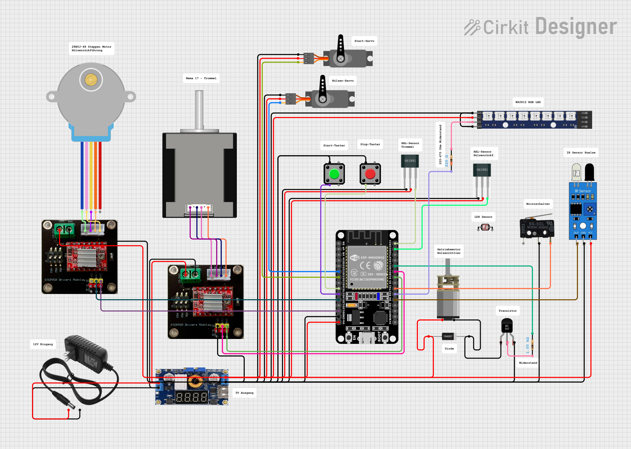
Automatic Cigarette Machine Circuit Documentation
Summary
This document provides a detailed overview of the Automatic Cigarette Machine circuit. The circuit is designed to automate the process of making cigarettes using an ESP32 microcontroller. It interfaces with various sensors and actuators, including Hall sensors, IR sensors, pushbuttons, servos, stepper motors, and an RGB LED matrix.
Component List
Hall Sensor
- Pins: -, +, S
- Description: Detects magnetic fields.
- Purpose: Used to detect the position of the drum and the presence of cigarette tubes.
Regulator XL 4015 with LCD Display with heatsink
- Pins: IN +, IN -, OUT +, OUT -
- Description: Voltage regulator with an LCD display.
- Purpose: Provides regulated power to the circuit components.
DC Mini Metal Gear Motor
- Pins: IN1, IN2
- Description: Small DC motor with metal gears.
- Purpose: Drives mechanical parts of the machine.
BC547 Transistor
- Pins: Collector, Base, Emitter
- Description: NPN transistor.
- Purpose: Used for switching and amplification.
1N4007 Rectifier Diode
- Pins: Cathode, Anode
- Description: General-purpose rectifier diode.
- Purpose: Protects against reverse voltage.
12v power supply
- Pins: +, -
- Description: Provides 12V DC power.
- Purpose: Powers the entire circuit.
Servo
- Pins: GND, VCC, PWM
- Description: Standard servo motor.
- Purpose: Controls the loading and starting mechanisms.
Nema 17 42-STH48
- Pins: A2 (black), A1 Green, B2 Red, B1 Blue
- Description: Stepper motor.
- Purpose: Drives the drum rotation.
28BYJ-48 Stepper Motor
- Pins: BLUE, PINK, YELLOW, ORANGE, RED
- Description: Small stepper motor.
- Purpose: Drives the cigarette tube loading mechanism.
Pushbutton
- Pins: Pin 2, Pin 1, Pin 3, Pin 4
- Description: Standard pushbutton.
- Purpose: Used for start and stop controls.
WS2812 RGB LED matrix 1x8
- Pins: VCC, GND, DOUT, DIN
- Description: RGB LED matrix.
- Purpose: Provides visual feedback.
Resistor
- Pins: pin1, pin2
- Description: Resistor.
- Purpose: Limits current flow.
- Properties: 220 Ohms, 1000 Ohms
ir sensor
- Pins: out, gnd, vcc
- Description: Infrared sensor.
- Purpose: Detects the presence of objects.
Photocell (LDR)
- Pins: pin 0, pin 1
- Description: Light-dependent resistor.
- Purpose: Detects light levels.
Micro Switch
- Pins: COM, NO, NC
- Description: Small switch.
- Purpose: Used for end-stop detection.
A4988 on Breakout Board
- Pins: VIN (12-24V), GND, 2B, 2A, 1A, 1B, ENABLE, STEP, DIR, VDD (5V)
- Description: Stepper motor driver.
- Purpose: Drives the stepper motors.
ESP32 (30 pin)
- Pins: EN, VP, VN, D34, D35, D32, D33, D25, D26, D27, D14, D12, D13, GND, Vin, D23, D22, TX0, RX0, D21, D19, D18, D5, TX2, RX2, D4, D2, D15, 3V3
- Description: Microcontroller.
- Purpose: Controls the entire circuit.
Wiring Details
Hall Sensor
- Pin -: Connected to GND.
- Pin +: Connected to OUT + of the Regulator XL 4015.
- Pin S: Connected to D23 (for one sensor) and D22 (for another sensor) of the ESP32.
Regulator XL 4015 with LCD Display with heatsink
- Pin IN +: Connected to + of the 12v power supply.
- Pin IN -: Connected to - of the 12v power supply.
- Pin OUT +: Connected to IN1 of the DC Mini Metal Gear Motor, + of the Hall Sensors, VCC of the Servos, VCC of the WS2812 RGB LED matrix, Anode of the 1N4007 Rectifier Diode, Vin of the ESP32, VIN (12-24V) of the A4988 on Breakout Board, and vcc of the ir sensor.
- Pin OUT -: Connected to ENABLE of the A4988 on Breakout Board, NO of the Micro Switch, - of the Hall Sensors, GND of the Servos, Emitter of the BC547 Transistor, Pin 1 of the Pushbuttons, GND of the WS2812 RGB LED matrix, GND of the ESP32, GND of the A4988 on Breakout Board, and gnd of the ir sensor.
DC Mini Metal Gear Motor
- Pin IN1: Connected to OUT + of the Regulator XL 4015.
- Pin IN2: Connected to Collector of the BC547 Transistor.
BC547 Transistor
- Collector: Connected to IN2 of the DC Mini Metal Gear Motor and Cathode of the 1N4007 Rectifier Diode.
- Base: Connected to pin1 of the 1000 Ohms Resistor.
- Emitter: Connected to OUT - of the Regulator XL 4015.
1N4007 Rectifier Diode
- Cathode: Connected to Collector of the BC547 Transistor.
- Anode: Connected to OUT + of the Regulator XL 4015.
12v power supply
- Pin +: Connected to IN + of the Regulator XL 4015.
- Pin -: Connected to IN - of the Regulator XL 4015.
Servo
- Pin GND: Connected to OUT - of the Regulator XL 4015.
- Pin VCC: Connected to OUT + of the Regulator XL 4015.
- Pin PWM: Connected to D32 (for one servo) and D33 (for another servo) of the ESP32.
Nema 17 42-STH48
- Pin A2 (black): Connected to 2A of the A4988 on Breakout Board.
- Pin A1 Green: Connected to 1A of the A4988 on Breakout Board.
- Pin B2 Red: Connected to 2B of the A4988 on Breakout Board.
- Pin B1 Blue: Connected to 1B of the A4988 on Breakout Board.
28BYJ-48 Stepper Motor
- Pin BLUE: Connected to 2B of the A4988 on Breakout Board.
- Pin PINK: Connected to 1B of the A4988 on Breakout Board.
- Pin YELLOW: Connected to 2A of the A4988 on Breakout Board.
- Pin ORANGE: Connected to 1A of the A4988 on Breakout Board.
- Pin RED: Not connected.
Pushbutton
- Pin 2: Connected to D26 (for one button) and D27 (for another button) of the ESP32.
- Pin 1: Connected to OUT - of the Regulator XL 4015.
- Pin 3: Not connected.
- Pin 4: Not connected.
WS2812 RGB LED matrix 1x8
- Pin VCC: Connected to OUT + of the Regulator XL 4015.
- Pin GND: Connected to OUT - of the Regulator XL 4015.
- Pin DOUT: Not connected.
- Pin DIN: Connected to pin2 of the 220 Ohms Resistor.
Resistor
- Pin1: Connected to Base of the BC547 Transistor and RX2 of the ESP32.
- Pin2: Connected to DIN of the WS2812 RGB LED matrix and D21 of the ESP32.
ir sensor
- Pin out: Connected to D4 of the ESP32.
- Pin gnd: Connected to OUT - of the Regulator XL 4015.
- Pin vcc: Connected to OUT + of the Regulator XL 4015.
Photocell (LDR)
- Pin 0: Not connected.
- Pin 1: Not connected.
Micro Switch
- Pin COM: Not connected.
- Pin NO: