Arduino Mega 2560 Controlled Multi-Temperature Monitoring and Motor Management System with Bluetooth Connectivity
Circuit Documentation
Summary
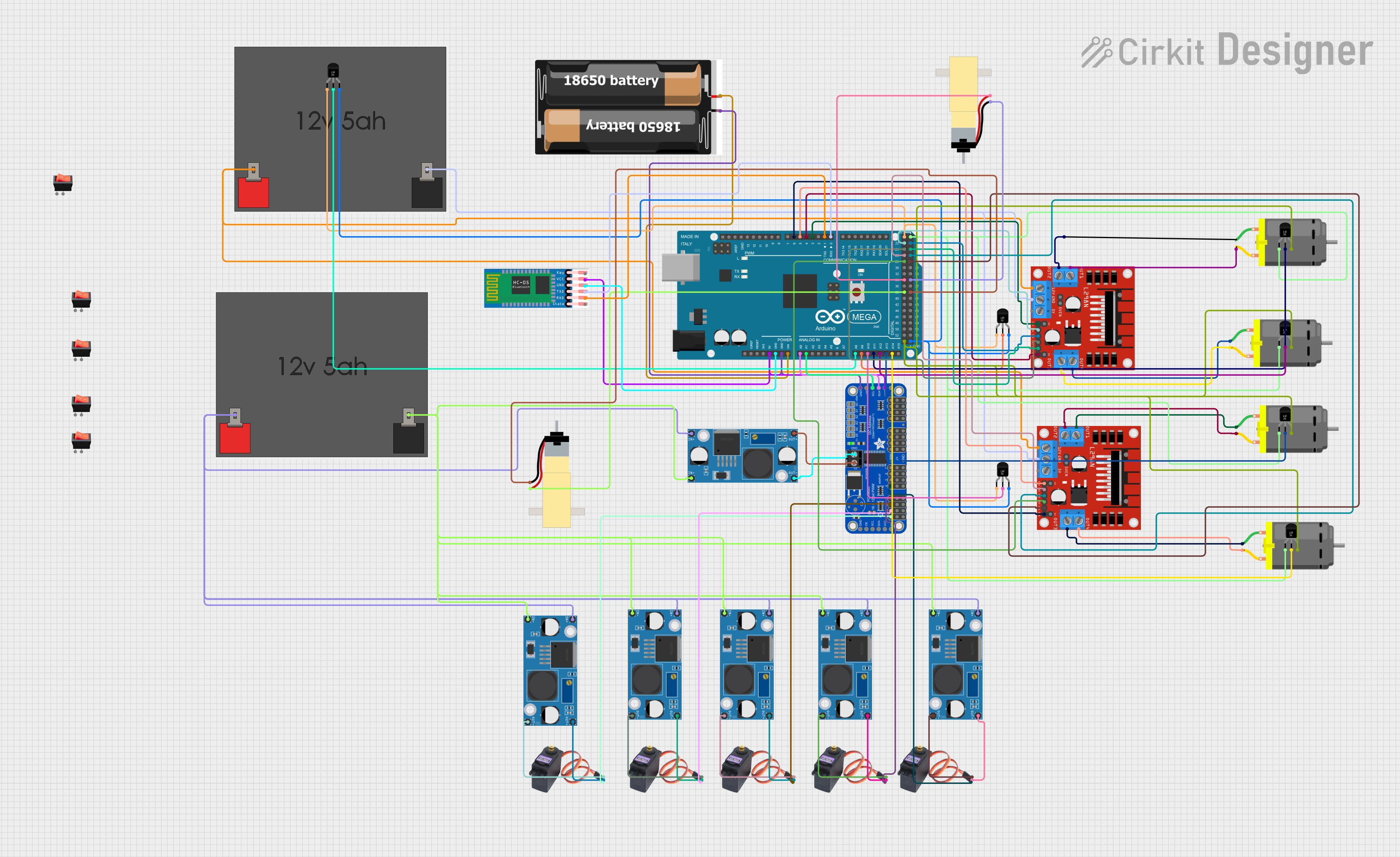
This circuit is designed to interface an Arduino Mega 2560 with various components including servo motors (MG996R), DC motors, temperature sensors (LM35), a motor driver (L298N), a Bluetooth module (HC-05), batteries, buck converters (LM2956), a PWM servo breakout board (Adafruit PCA9685), and rocker switches. The circuit is powered by 12V batteries and uses buck converters to step down the voltage for the servo motors. The Arduino Mega 2560 controls the motors and reads temperature data from the LM35 sensors. Communication with external devices is facilitated by the HC-05 Bluetooth module.
Component List
- Arduino Mega 2560: A microcontroller board based on the ATmega2560, with numerous digital and analog I/O pins.
- MG996R Servo Motors: High-torque digital servos for precise control of mechanical components.
- DC Motors: Electric motors that run on direct current (DC) electricity.
- Temperature Sensors (LM35): Precision temperature sensors with an analog output proportional to the temperature.
- L298N DC Motor Driver: A dual H-bridge motor driver that can drive two DC motors or one stepper motor.
- 12V 5Ah Batteries: Lead-acid batteries providing a 12V power source for the circuit.
- Hobby Gearmotors with 48:1 Gearbox: DC motors with an integrated gearbox for increased torque.
- 2x 18650 Battery Pack: A battery pack consisting of two 18650 lithium-ion cells.
- LM2956 Buck Converter DC-DC: A buck converter module that steps down voltage from a higher level to a lower level.
- Adafruit PCA9685 PWM Servo Breakout: A 16-channel, 12-bit PWM Fm+ I2C-bus LED controller ideal for driving servos.
- HC-05 Bluetooth Module: A wireless Bluetooth transceiver module for serial communication.
- Rocker Switches: Simple on/off switches to control the power flow in the circuit.
Wiring Details
Arduino Mega 2560
- 5V: Powers the Adafruit PCA9685, HC-05, and LM35 temperature sensors.
- GND: Common ground for HC-05, Adafruit PCA9685, and LM35 temperature sensors.
- VIN: Connected to the 2x 18650 battery pack.
- A0-A14: Analog inputs connected to various LM35 temperature sensors.
- D0 RX0: Receives data from HC-05 TXD.
- D1 TX0: Transmits data to HC-05 RXD.
- D3, D4, D5, D6 PWM: PWM outputs to control the ENA and ENB pins of the L298N motor drivers.
- D22-D29, D34-D39: Digital outputs to control IN1-IN4 pins of the L298N motor drivers.
MG996R Servo Motors
- VCC: Powered by LM2956 buck converters.
- GND: Connected to the ground of their respective LM2956 buck converters.
- SIG: Signal inputs connected to PWM outputs of the Adafruit PCA9685.
DC Motors
- Connected to OUT1-OUT4 of the L298N motor drivers.
Temperature Sensors (LM35)
- +Vs: Powered by the 5V output from the Arduino Mega 2560.
- Vout: Analog voltage output connected to the analog inputs A8-A14 of the Arduino Mega 2560.
- GND: Common ground with the Arduino Mega 2560.
L298N DC Motor Driver
- ENA, ENB: Enable pins controlled by PWM outputs D3, D4, D5, D6 of the Arduino Mega 2560.
- IN1-IN4: Input pins controlled by digital outputs D22-D29, D34-D39 of the Arduino Mega 2560.
- OUT1-OUT4: Outputs connected to DC motors.
- 12V: Powered by the 12V 5Ah batteries.
- GND: Common ground with the 12V 5Ah batteries.
12V 5Ah Batteries
- 12v +: Powers the L298N motor drivers and the input of the LM2956 buck converters.
- 12v -: Common ground for the L298N motor drivers and the input of the LM2956 buck converters.
LM2956 Buck Converter DC-DC
- IN+: Connected to the 12v + of the 12V 5Ah batteries.
- IN-: Connected to the 12v - of the 12V 5Ah batteries.
- OUT+: Powers the Adafruit PCA9685 and MG996R servos.
- OUT-: Common ground for the Adafruit PCA9685 and MG996R servos.
Adafruit PCA9685 PWM Servo Breakout
- VCC: Powered by the 5V output from the Arduino Mega 2560.
- GND: Common ground with the Arduino Mega 2560.
- SDA, SCL: I2C communication with the Arduino Mega 2560 (connected to A0, A1).
- PWM0-PWM4: PWM outputs to control MG996R servos.
HC-05 Bluetooth Module
- VCC: Powered by the 5V output from the Arduino Mega 2560.
- GND: Common ground with the Arduino Mega 2560.
- TXD: Transmits data to Arduino Mega 2560 RX0.
- RXD: Receives data from Arduino Mega 2560 TX0.
Rocker Switches
- Not detailed in the net list, assumed to be used for power control.
Documented Code
void setup() {
  // put your setup code here, to run once:

}

void loop() {
  // put your main code here, to run repeatedly:

}
The provided code is a template with empty setup() and loop() functions, which are the standard structure for Arduino sketches. The setup() function is intended to contain initialization code that runs once when the program starts, such as pin mode declarations. The loop() function is for code that runs continuously, containing the main logic of the program. Additional code is required to control the components as per the circuit design.