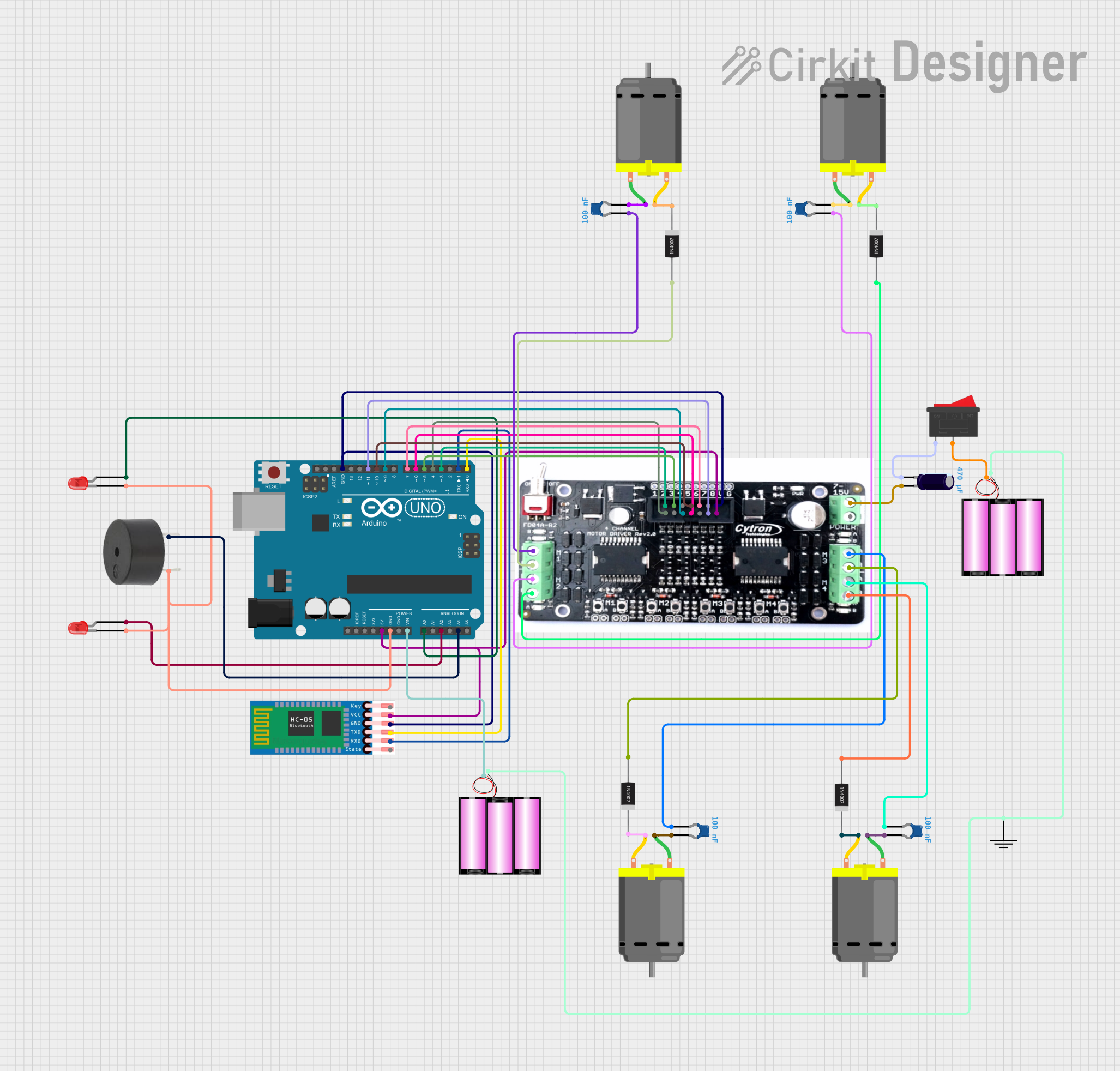
Arduino UNO Bluetooth-Controlled Robot Car

Circuit Documentation
Summary of the Circuit
This circuit is designed to control a 4-wheeled robot car via Bluetooth communication. The car is capable of moving in different directions (forward, backward, left, and right) based on commands received from a mobile app. It also features front and back lights that can be toggled on or off, as well as a buzzer for auditory signals. The core of the control system is an Arduino UNO microcontroller, which interfaces with an HC-05 Bluetooth module for wireless communication. The motor driver controls the DC motors responsible for the car's movement, while the capacitors and diodes are used for noise suppression and protecting the circuit from voltage spikes, respectively.
Component List
Microcontroller
- Arduino UNO: A microcontroller board based on the ATmega328P, used for controlling the various components of the robot car.
Communication Module
- HC-05 Bluetooth Module: A wireless communication module that allows the Arduino to communicate with a mobile app via Bluetooth.
Motor Driver
- 4 Channel Motor Driver: Controls the direction and speed of the DC motors.
Motors
- DC Motors (x4): Provide the movement for the robot car.
Power Supply
- 12V Batteries (x2): Provide the power required for the motors and the entire circuit.
Capacitors
- Ceramic Capacitors (x4): Used for noise suppression on the power lines.
- Electrolytic Capacitor: Provides stability to the power supply.
Diodes
- 1N4007 Rectifier Diodes (x4): Protect the motors and the motor driver from voltage spikes caused by back EMF.
Indicators and Sound
- LEDs (Red, x2): Serve as indicators for the front and back lights of the robot car.
- Buzzer: Used to generate auditory signals.
Switch
- Rocker Switch: Allows for manual power control to the circuit.
Ground Reference
- GND: A common ground reference point for the circuit.
Wiring Details
Arduino UNO
- 5V: Powers the HC-05 Bluetooth module and the 4 Channel Motor Driver.
- GND: Common ground for LEDs, buzzer, HC-05, and the motor driver.
- Vin: Connected to the positive terminal of the 12V battery.
- Digital Pins (D0-D11): Control signals for the motor driver and communication with the HC-05 module.
- Analog Pins (A0, A2, A4): Control the front light, back light, and buzzer.
HC-05 Bluetooth Module
- VCC: Powered by the 5V output from the Arduino.
- GND: Connected to the common ground.
- TXD: Transmits data to the Arduino's RX (D0).
- RXD: Receives data from the Arduino's TX (D1).
4 Channel Motor Driver
- V: Powered by the 5V output from the Arduino.
- G: Connected to the common ground.
- Input Pins (1-8): Receive control signals from the Arduino's digital pins (D3-D11).
- Motor Outputs (A, B): Connected to the DC motors and associated capacitors and diodes.
DC Motors
- Pin 1: Connected to the motor driver outputs and one terminal of the ceramic capacitors.
- Pin 2: Connected to the cathode of the rectifier diodes.
Ceramic Capacitors
- Pin 0: Connected to the motor driver outputs (A or B).
- Pin 1: Connected to one of the terminals of the DC motors.
Electrolytic Capacitor
- +: Connected to the positive terminal of the motor driver.
- -: Connected to the rocker switch.
1N4007 Rectifier Diodes
- Anode: Connected to the motor driver outputs (B).
- Cathode: Connected to one of the terminals of the DC motors.
LEDs (Red)
- Cathode: Connected to the common ground.
- Anode: Connected to the Arduino's analog pins (A0 for the front light, A2 for the back light).
Buzzer
- PIN: Connected to the common ground.
- GND: Connected to the Arduino's analog pin A4.
Rocker Switch
- Pin 1: Connected to the negative terminal of one 12V battery.
- Pin 2: Connected to the positive terminal of the other 12V battery.
Batteries (12V)
- +: One battery connected to the Arduino Vin and the other to the rocker switch.
- -: Both batteries connected to the common ground reference point.
Documented Code
/*
 * Arduino Sketch for a 4-wheeled robot car controlled via Bluetooth.
 * The car can move forward, backward, left, and right based on commands
 * received from a mobile app. It also has front and back lights that can
 * be switched on or off via the app.
 */

#include <SoftwareSerial.h>

// Pin definitions
const int LF = 4; // Left Forward
const int LB = 5; // Left Backward
const int RF = 6; // Right Forward
const int RB = 7; // Right Backward
const int frontLight = A0; // Front Light
const int backLight = A2; // Back Light
const int buzzer = A4; // Buzzer

SoftwareSerial BTSerial(0, 1); // RX, TX

void setup() {
  // Initialize serial communication
  Serial.begin(9600);
  BTSerial.begin(9600);

  // Initialize pins
  pinMode(LF, OUTPUT);
  pinMode(LB, OUTPUT);
  pinMode(RF, OUTPUT);
  pinMode(RB, OUTPUT);
  pinMode(frontLight, OUTPUT);
  pinMode(backLight, OUTPUT);
  pinMode(buzzer, OUTPUT);

  // Initial state
  digitalWrite(frontLight, LOW);
  digitalWrite(backLight, LOW);
  digitalWrite(buzzer, LOW);
  Serial.println("Car is Ready");
}

void loop() {
  if (BTSerial.available()) {
    char command = BTSerial.read();
    Serial.print("Command: ");
    Serial.println(command);

    switch (command) {
      case 'F':
        moveForward();
        break;
      case 'B':
        moveBackward();
        break;
      case 'L':
        turnLeft();
        break;
      case 'R':
        turnRight();
        break;
      case 'S':
        stopCar();
        break;
      case '1':
        digitalWrite(frontLight, HIGH);
        break;
      case '0':
        digitalWrite(frontLight, LOW);
        break;
      case '3':
        digitalWrite(backLight, HIGH);
        break;
      case '2':
        digitalWrite(backLight, LOW);
        break;
      default:
        Serial.println("Unknown command");
        break;
    }
  }
}

void moveForward() {
  Serial.println("Moving forward");
  digitalWrite(LF, HIGH);
  digitalWrite(RF, HIGH);
  digitalWrite(LB, LOW);
  digitalWrite(RB, LOW);
}

void moveBackward() {
  Serial.println("Moving backward");
  digitalWrite(LB, HIGH);
  digitalWrite(RB, HIGH);
  digitalWrite(LF, LOW);
  digitalWrite(RF, LOW);
}

void turnLeft() {
  Serial.println("Turning left");
  digitalWrite(LF, LOW);
  digitalWrite(RF, HIGH);
  digitalWrite(LB, HIGH);
  digitalWrite(RB, LOW);
}

void turnRight() {
  Serial.println("Turning right");
  digitalWrite(LF, HIGH);
  digitalWrite(RF, LOW);
  digitalWrite(LB, LOW);
  digitalWrite(RB, HIGH);
}

void stopCar() {
  Serial.println("Stopping");
  digitalWrite(LF, LOW);
  digitalWrite(RF, LOW);
  digitalWrite(LB, LOW);
  digitalWrite(RB, LOW);
}
This code is responsible for interpreting Bluetooth commands and controlling the robot car's movements and features accordingly. It sets up the necessary pins as outputs and initializes the SoftwareSerial library for Bluetooth communication. The loop function listens for incoming commands and calls the appropriate functions to control the car.