
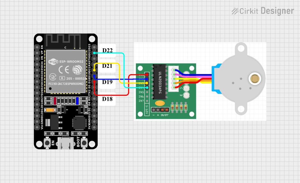
Circuit Documentation
Summary
This circuit involves an ESP32 microcontroller and a stepper motor. The ESP32 is used to control the stepper motor by sending signals to its input pins. The circuit is designed to demonstrate basic motor control using an ESP32.
Component List
ESP32 (30 pin)
- Description: A powerful microcontroller with built-in Wi-Fi and Bluetooth capabilities.
- Pins: EN, VP, VN, D34, D35, D32, D33, D25, D26, D27, D14, D12, D13, GND, Vin, D23, D22, TX0, RX0, D21, D19, D18, D5, TX2, RX2, D4, D2, D15, 3V3
Stepper Motor One
- Description: A stepper motor with four input pins for controlling the motor phases.
- Pins: IN1, IN2, IN3, IN4, +, -
Comment
- Description: Placeholder for comments in the circuit design.
- Pins: None
Wiring Details
ESP32 (30 pin)
- D22 is connected to IN4 of the Stepper Motor One.
- D21 is connected to IN3 of the Stepper Motor One.
- D19 is connected to IN2 of the Stepper Motor One.
- D18 is connected to IN1 of the Stepper Motor One.
Stepper Motor One
- IN4 is connected to D22 of the ESP32.
- IN3 is connected to D21 of the ESP32.
- IN2 is connected to D19 of the ESP32.
- IN1 is connected to D18 of the ESP32.
Documented Code
ESP32 (30 pin)
void setup() {
  // put your setup code here, to run once:

}

void loop() {
  // put your main code here, to run repeatedly:

}
Stepper Motor One
void setup() {
  // put your setup code here, to run once:

}

void loop() {
  // put your main code here, to run repeatedly:

}
This documentation provides a comprehensive overview of the circuit, including a summary, detailed component list, wiring details, and the code used for the microcontrollers.