
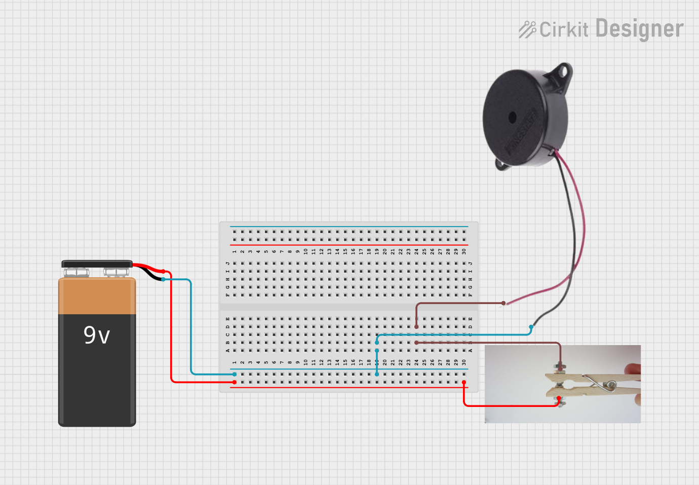
Circuit Documentation
Summary of the Circuit
This circuit is a simple Morse code generator that uses a 9V battery, a Morse switch, and a buzzer. When the Morse switch is closed, the circuit is completed, and the buzzer is activated, allowing the user to generate Morse code signals by pressing the switch in the pattern of dots and dashes.
Component List
9V Battery
- Description: A standard 9V battery used as the power source for the circuit.
- Pins:
- Negative (-)
- Positive (+)
- Purpose: Provides the necessary voltage to power the buzzer when the Morse switch is closed.
Morse Switch
- Description: A switch used to open and close the electrical circuit manually.
- Pins:
- Live
- Switch
- Purpose: Allows the user to control the activation of the buzzer to generate Morse code.
Buzzer
- Description: An electromechanical component that emits sound when powered.
- Pins:
- POSITIVE
- NEGATIVE
- Purpose: Converts electrical signals into audible sound, which is used to generate Morse code signals.
Wiring Details
9V Battery
- Positive (+) pin is connected to the Live pin of the Morse Switch.
- Negative (-) pin is connected to the NEGATIVE pin of the Buzzer.
Morse Switch
- Live pin is connected to the Positive (+) pin of the 9V Battery.
- Switch pin is connected to the POSITIVE pin of the Buzzer.
Buzzer
- POSITIVE pin is connected to the Switch pin of the Morse Switch.
- NEGATIVE pin is connected to the Negative (-) pin of the 9V Battery.
Documented Code
There is no microcontroller or embedded code associated with this circuit. The functionality is purely hardware-based, relying on the physical operation of the Morse switch to control the buzzer.