Cirkit Designer
Your all-in-one circuit design IDE
Home /
Project Documentation
Arduino-Based Solar and Piezo Energy Harvesting System with Rain Sensor and Motor Control
Circuit Documentation
Summary
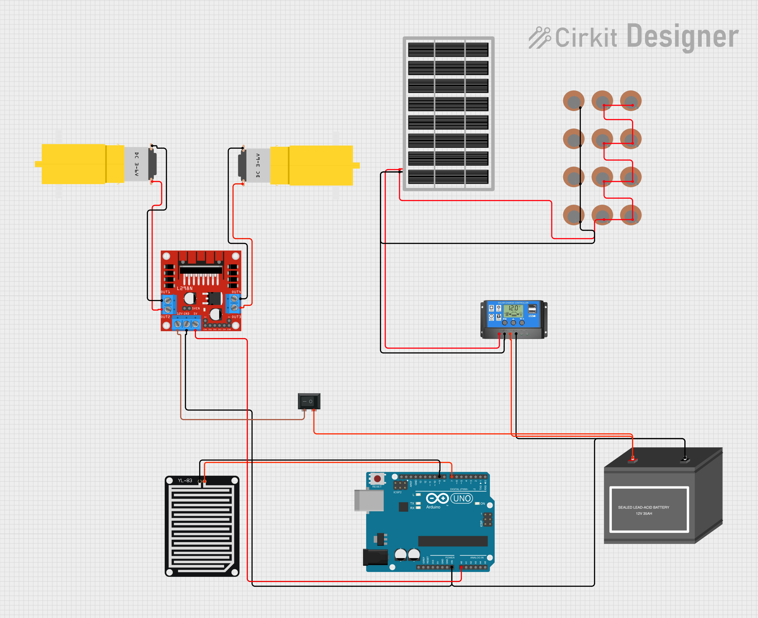
This document provides a detailed overview of an Arduino-based combined piezoelectric and solar PV energy harvesting system. The system includes a rain sensor, motor drive module, solar charger controller, switch, and 12V battery storage. The Arduino microcontroller reads the rain sensor and controls the motor driver accordingly. It also monitors the piezo sensors and solar panel for energy harvesting.
Component List
Arduino UNO
- Description: Microcontroller board based on the ATmega328P.
- Pins: UNUSED, IOREF, Reset, 3.3V, 5V, GND, Vin, A0, A1, A2, A3, A4, A5, SCL, SDA, AREF, D13, D12, D11, D10, D9, D8, D7, D6, D5, D4, D3, D2, D1, D0
YL-83 Rain Sensor - Detection Board
- Description: Rain detection sensor.
- Pins: POS, NEG
L298N DC Motor Driver
- Description: Dual H-Bridge motor driver.
- Pins: OUT1, OUT2, 12V, GND, 5V, OUT3, OUT4, 5V-ENA-JMP-I, 5V-ENA-JMP-O, +5V-J1, +5V-J2, ENA, IN1, IN2, IN3, IN4, ENB
Motor amarillo motorreductor hobby
- Description: Hobby DC motor with gearbox.
- Pins: vcc, GND
Solar Panel
- Description: Solar panel for energy harvesting.
- Pins: gnd, vcc
Solar Charge Controller
- Description: Controller for managing solar panel and battery charging.
- Pins: Solar Cell +, Solar Cell -, Battery +, Battery -, Load +, Load -
Piezo Sensor
- Description: Sensor for piezoelectric energy harvesting.
- Pins: +, -
12V Battery (mini)
- Description: 12V battery for energy storage.
- Pins: -, +
Rocker Switch (SPST)
- Description: Single-pole single-throw switch.
- Pins: 1, 2
Wiring Details
Arduino UNO
- Vin connected to GND of L298N DC motor driver, - of 12V Battery, and Battery - of Solar Charge Controller.
- A0 connected to 5V of L298N DC motor driver.
- D9 connected to POS of YL-83 Rain Sensor.
- D7 connected to NEG of YL-83 Rain Sensor.
YL-83 Rain Sensor - Detection Board
- POS connected to D9 of Arduino UNO.
- NEG connected to D7 of Arduino UNO.
L298N DC Motor Driver
- GND connected to Vin of Arduino UNO, - of 12V Battery, and Battery - of Solar Charge Controller.
- 5V connected to A0 of Arduino UNO.
- OUT1 connected to GND of Motor amarillo motorreductor hobby.
- OUT2 connected to vcc of Motor amarillo motorreductor hobby.
- 12V connected to 2 of Rocker Switch.
- OUT3 connected to GND of Motor amarillo motorreductor hobby.
- OUT4 connected to vcc of Motor amarillo motorreductor hobby.
Motor amarillo motorreductor hobby
- GND connected to OUT1 of L298N DC motor driver.
- vcc connected to OUT2 of L298N DC motor driver.
- GND connected to OUT3 of L298N DC motor driver.
- vcc connected to OUT4 of L298N DC motor driver.
Solar Panel
- gnd connected to Solar Cell - of Solar Charge Controller.
- vcc connected to Solar Cell + of Solar Charge Controller.
Solar Charge Controller
- Solar Cell - connected to gnd of Solar Panel.
- Solar Cell + connected to vcc of Solar Panel.
- Battery - connected to GND of L298N DC motor driver, Vin of Arduino UNO, and - of 12V Battery.
- Battery + connected to + of 12V Battery and 1 of Rocker Switch.
Piezo Sensor
- - connected to Solar Cell - of Solar Charge Controller.
- + connected to Solar Cell + of Solar Charge Controller.
12V Battery (mini)
- - connected to GND of L298N DC motor driver, Vin of Arduino UNO, and Battery - of Solar Charge Controller.
- + connected to Battery + of Solar Charge Controller and 1 of Rocker Switch.
Rocker Switch (SPST)
- 1 connected to + of 12V Battery and Battery + of Solar Charge Controller.
- 2 connected to 12V of L298N DC motor driver.
Documented Code
Arduino UNO Code
/*
 * Arduino Based Combined Piezoelectric and Solar PV Energy Harvesting System
 * with Rain Sensor, Motor Drive Module, Solar Charger Controller, Switch, and
 * 12V Battery Storage
 *
 * This code reads the rain sensor and controls the motor driver accordingly.
 * It also monitors the piezo sensors and solar panel for energy harvesting.
 */

// Pin definitions
const int rainSensorPin = 7; // Rain sensor connected to D7
const int motorEnablePin = 9; // Motor driver enable pin connected to D9
const int motorControlPin1 = 2; // Motor control pin 1 connected to D2
const int motorControlPin2 = 3; // Motor control pin 2 connected to D3

void setup() {
  // Initialize motor control pins as outputs
  pinMode(motorControlPin1, OUTPUT);
  pinMode(motorControlPin2, OUTPUT);
  // Initialize rain sensor pin as input
  pinMode(rainSensorPin, INPUT);
  // Initialize motor enable pin as output
  pinMode(motorEnablePin, OUTPUT);
  // Start with motors disabled
  digitalWrite(motorEnablePin, LOW);
}

void loop() {
  // Read the rain sensor value
  int rainSensorValue = digitalRead(rainSensorPin);
  if (rainSensorValue == HIGH) {
    // If rain is detected, stop the motors
    stopMotors();
  } else {
    // If no rain, run the motors
    runMotors();
  }
  delay(1000); // Wait for 1 second before next check
}

void stopMotors() {
  digitalWrite(motorEnablePin, LOW);
  digitalWrite(motorControlPin1, LOW);
  digitalWrite(motorControlPin2, LOW);
}

void runMotors() {
  digitalWrite(motorEnablePin, HIGH);
  digitalWrite(motorControlPin1, HIGH);
  digitalWrite(motorControlPin2, LOW);
}
YL-83 Rain Sensor - Detection Board Code
/*
 * Arduino Based Combined Piezoelectric and Solar PV Energy Harvesting System
 * with Rain Sensor, Motor Drive Module, Switch, Solar Charger Controller, and
 * 12V Battery Storage
 *
 * This code reads the rain sensor and controls the motor driver accordingly.
 * It also monitors the piezo sensors and solar panel for energy harvesting.
 */

// Pin definitions
const int rainSensorPin = 7; // Rain sensor connected to D7
const int motorEnablePin = 9; // Motor driver enable pin connected to D9
const int motorControlPin1 = 2; // Motor control pin 1 connected to D2
const int motorControlPin2 = 3; // Motor control pin 2 connected to D3

void setup() {
  // Initialize motor control pins as outputs
  pinMode(motorControlPin1, OUTPUT);
  pinMode(motorControlPin2, OUTPUT);
  // Initialize rain sensor pin as input
  pinMode(rainSensorPin, INPUT);
  // Initialize motor enable pin as output
  pinMode(motorEnablePin, OUTPUT);
  // Start with motors disabled
  digitalWrite(motorEnablePin, LOW);
}

void loop() {
  // Read the rain sensor value
  int rainSensorValue = digitalRead(rainSensorPin);
  if (rainSensorValue == HIGH) {
    // If rain is detected, stop the motors
    stopMotors();
  } else {
    // If no rain, run the motors
    runMotors();
  }
  delay(1000); // Wait for 1 second before next check
}

void stopMotors() {
  digitalWrite(motorEnablePin, LOW);
  digitalWrite(motorControlPin1, LOW);
  digitalWrite(motorControlPin2, LOW);
}

void runMotors() {
  digitalWrite(motorEnablePin, HIGH);
  digitalWrite(motorControlPin