
Arduino Mega 2560-Based Smart LED Control System with Fingerprint Scanner and OLED Display
View and Edit Project In Cirkit Designer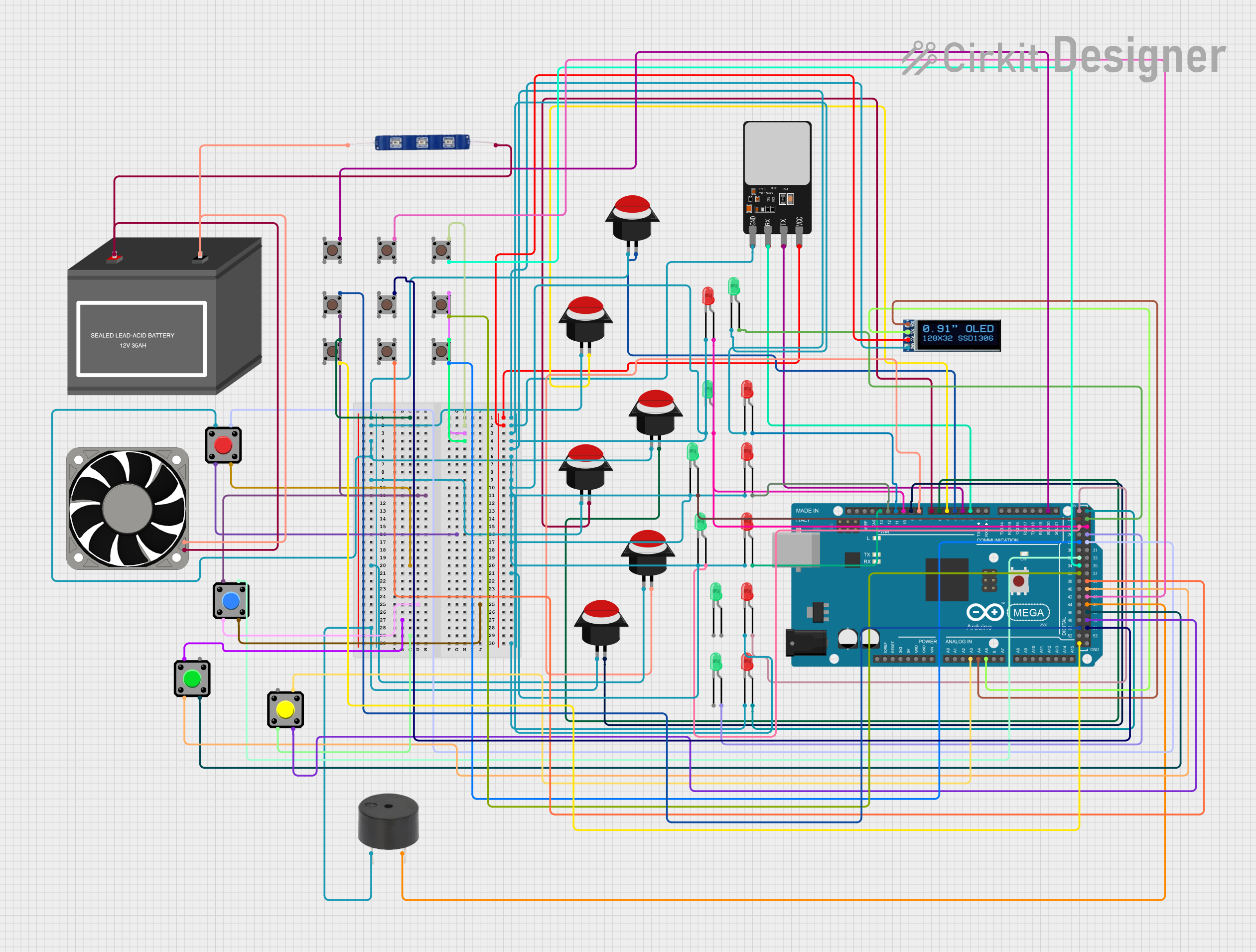
Circuit Documentation
Summary
This circuit involves an Arduino Mega 2560 microcontroller interfacing with multiple LEDs, push buttons, a fingerprint scanner, an OLED display, a buzzer, a 12V battery, a 12V fan, and a 12V blue LED. The circuit is designed to demonstrate basic input and output operations, including reading button presses, controlling LEDs, and interfacing with a fingerprint scanner and an OLED display.
Component List
Arduino Mega 2560
- Description: A microcontroller board based on the ATmega2560.
- Pins: IOREF, RESET, 3V3, 5V, GND, VIN, A0-A15, D0-D53, AREF, SDA, SCL
LED: Two Pin (green)
- Description: A green LED with two pins.
- Pins: cathode, anode
LED: Two Pin (red)
- Description: A red LED with two pins.
- Pins: cathode, anode
Push Button Round
- Description: A round push button with two legs.
- Pins: leg0, leg1
Pushbutton
- Description: A push button with four pins.
- Pins: Pin 1 (in), Pin 2 (in), Pin 3 (out), Pin 4 (out)
Fingerprint Scanner
- Description: A fingerprint scanner module.
- Pins: VCC, TX, RX, GND
OLED Display 128x32
- Description: An OLED display module with 128x32 resolution.
- Pins: SDA, SCL, VCC, GND
Buzzer
- Description: A buzzer module.
- Pins: PIN, GND
12V Battery (mini)
- Description: A mini 12V battery.
- Pins: -, +
40 Fan 12V
- Description: A 12V fan.
- Pins: +12V, -12V
12V Blue LED
- Description: A blue LED designed for 12V operation.
- Pins: GND, VCC
Wiring Details
Arduino Mega 2560
- A3: Connected to Pushbutton Pin 4
- A4: Connected to OLED Display SDA
- A5: Connected to OLED Display SCL
- D2 PWM: Connected to Fingerprint Scanner RX
- D3 PWM: Connected to Fingerprint Scanner TX
- D4 PWM: Connected to Push Button Round leg1
- D5 PWM: Connected to Push Button Round leg1
- D6 PWM: Connected to Push Button Round leg1
- D7 PWM: Connected to Push Button Round leg1
- D8 PWM: Connected to Push Button Round leg1
- D9 PWM: Connected to Push Button Round leg1
- D10 PWM: Connected to LED (red) anode
- D11 PWM: Connected to LED (red) anode
- D12 PWM: Connected to LED (red) anode
- D13 PWM: Connected to LED (red) anode
- D20/SDA: Connected to Pushbutton Pin 3 (out)
- D22: Connected to LED (green) anode
- D23: Connected to LED (green) anode
- D24: Connected to LED (green) anode
- D25: Connected to LED (green) anode
- D27: Connected to LED (green) anode
- D28: Connected to Pushbutton Pin 4 (out)
- D29: Connected to Pushbutton Pin 4
- D32: Connected to Pushbutton Pin 4
- D34: Connected to Pushbutton Pin 4 (out)
- D36: Connected to Pushbutton Pin 4 (out)
- D39: Connected to Pushbutton Pin 4 (out)
- D41: Connected to Pushbutton Pin 2
- D43: Connected to Pushbutton Pin 3 (out)
- D45: Connected to Buzzer GND
- D47: Connected to Pushbutton Pin 3
- D49: Connected to Pushbutton Pin 3
- D50: Connected to Pushbutton Pin 3 (out)
- D51: Connected to Pushbutton Pin 3 (out)
- 5V: Connected to LED (red) anode
- GND: Connected to Pushbutton Pin 4 (out)
LED: Two Pin (green)
- cathode: Connected to GND
- anode: Connected to Arduino Mega 2560 D22, D23, D24, D25, D27
LED: Two Pin (red)
- cathode: Connected to GND
- anode: Connected to Arduino Mega 2560 D10 PWM, D11 PWM, D12 PWM, D13 PWM, 5V
Push Button Round
- leg0: Connected to Push Button Round leg0, Pushbutton Pin 1, Buzzer PIN
- leg1: Connected to Arduino Mega 2560 D4 PWM, D5 PWM, D6 PWM, D7 PWM, D8 PWM, D9 PWM
Pushbutton
- Pin 1 (in): Connected to Push Button Round leg0
- Pin 2 (in): Connected to Arduino Mega 2560 D41
- Pin 3 (out): Connected to Arduino Mega 2560 D20/SDA, D50, D51, D43, D49, D47
- Pin 4 (out): Connected to Arduino Mega 2560 A3, D28, D29, D32, D34, D36, D39, GND
Fingerprint Scanner
- VCC: Connected to OLED Display VCC
- TX: Connected to Arduino Mega 2560 D3 PWM
- RX: Connected to Arduino Mega 2560 D2 PWM
- GND: Connected to OLED Display GND, LED (green) cathode, LED (red) cathode
OLED Display 128x32
- SDA: Connected to Arduino Mega 2560 A4
- SCL: Connected to Arduino Mega 2560 A5
- VCC: Connected to Fingerprint Scanner VCC
- GND: Connected to Fingerprint Scanner GND
Buzzer
- PIN: Connected to Push Button Round leg0
- GND: Connected to Arduino Mega 2560 D45
12V Battery (mini)
- -: Connected to 12V Blue LED GND, 40 Fan 12V -12V
- +: Connected to 12V Blue LED VCC, 40 Fan 12V +12V
40 Fan 12V
- +12V: Connected to 12V Battery +
- -12V: Connected to 12V Battery -
12V Blue LED
- GND: Connected to 12V Battery -
- VCC: Connected to 12V Battery +
Documented Code
Arduino Mega 2560 Code
void setup() {
  // put your setup code here, to run once:

}

void loop() {
  // put your main code here, to run repeatedly:

}
This code is a basic template for the Arduino Mega 2560. The setup() function is used to initialize any settings or configurations, and the loop() function contains the main code that runs repeatedly.