Cirkit Designer
Your all-in-one circuit design IDE
Home /
Project Documentation
ESP32-Controlled Robotic Vehicle with Ultrasonic Navigation

Circuit Documentation
Summary
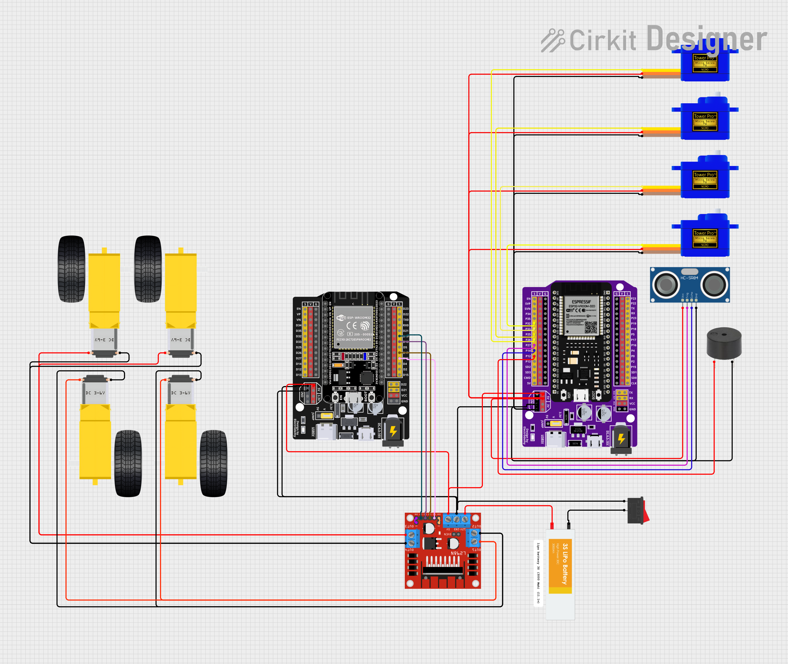
This circuit is designed to control multiple servomotors, a DC motor driver connected to gearmotors, and an ultrasonic sensor, all interfaced with an ESP32 microcontroller. The circuit includes a power supply from a Lipo battery and a rocker switch for power control. The ESP32 microcontroller is responsible for controlling the servomotors and reading sensor data, while the L298N DC motor driver is used to control the gearmotors. A buzzer is also included for audio feedback.
Component List
- ESP32 - 38 pins Expansion Board: A microcontroller board based on the ESP32 chip with 38 expansion pins.
- Lipo Battery: A rechargeable battery providing power to the circuit.
- Rocker Switch: A switch used to control the power supply to the circuit.
- L298N DC motor driver: A module for controlling DC motors with two H-bridges.
- Servomotor SG90: A small and lightweight servo motor for precise control.
- HC-SR04 Ultrasonic Sensor: A sensor for measuring distance via ultrasonic waves.
- Buzzer: An electronic component that produces sound.
- Gearmotor DC Wheels Right: A DC motor with a gear reduction mechanism.
Wiring Details
ESP32 - 38 pins Expansion Board
- P32 connected to Servomotor SG90 (Signal)
- P33 connected to Servomotor SG90 (Signal)
- P25 connected to Servomotor SG90 (Signal)
- P26 connected to Servomotor SG90 (Signal)
- P27 connected to HC-SR04 Ultrasonic Sensor (Trigger)
- P14 connected to HC-SR04 Ultrasonic Sensor (Echo)
- P12 connected to Buzzer (Signal)
- 5V connected to Servomotors SG90 (Power), HC-SR04 Ultrasonic Sensor (Power), and L298N DC motor driver (5V Input)
- G connected to Buzzer (Ground), Rocker Switch (Ground), and all Servomotors SG90 (Ground)
- GND connected to HC-SR04 Ultrasonic Sensor (Ground) and L298N DC motor driver (Ground)
Lipo Battery
- VCC connected to L298N DC motor driver (12V Input)
- GND connected to Rocker Switch
Rocker Switch
- Pin 1 connected to ESP32 - 38 pins Expansion Board (Ground)
- Pin 2 connected to Lipo Battery (Ground)
L298N DC motor driver
- OUT1/OUT2 connected to Gearmotor DC Wheels Right
- OUT3/OUT4 connected to Gearmotor DC Wheels Right
- ENA connected to +5V-J1 (Enable A)
- ENB connected to +5V-J2 (Enable B)
- IN1/IN2/IN3/IN4 connected to ESP32 - Expansion Board (Control Pins)
Servomotor SG90
- SIG connected to ESP32 - 38 pins Expansion Board (Control Pins)
- VCC connected to ESP32 - 38 pins Expansion Board (5V)
- GND connected to ESP32 - 38 pins Expansion Board (Ground)
HC-SR04 Ultrasonic Sensor
- TRIG connected to ESP32 - 38 pins Expansion Board (Trigger)
- ECHO connected to ESP32 - 38 pins Expansion Board (Echo)
- VCC connected to ESP32 - 38 pins Expansion Board (5V)
- GND connected to ESP32 - 38 pins Expansion Board (Ground)
Buzzer
- PIN connected to ESP32 - 38 pins Expansion Board (Signal)
- GND connected to ESP32 - 38 pins Expansion Board (Ground)
Gearmotor DC Wheels Right
- PIN1/PIN2 connected to L298N DC motor driver (Motor Outputs)
Documented Code
Microcontroller Code (sketch.ino)
void setup() {
  // put your setup code here, to run once:

}

void loop() {
  // put your main code here, to run repeatedly:

}
Additional Documentation (documentation.txt)
No additional documentation provided.
Please note that the above documentation is based on the provided JSON inputs and assumes standard wiring practices. The actual physical layout, wire colors, and other details may vary.