
Arduino-Controlled Relay Switch with Motor Driver and Temperature Sensing
View and Edit Project In Cirkit Designer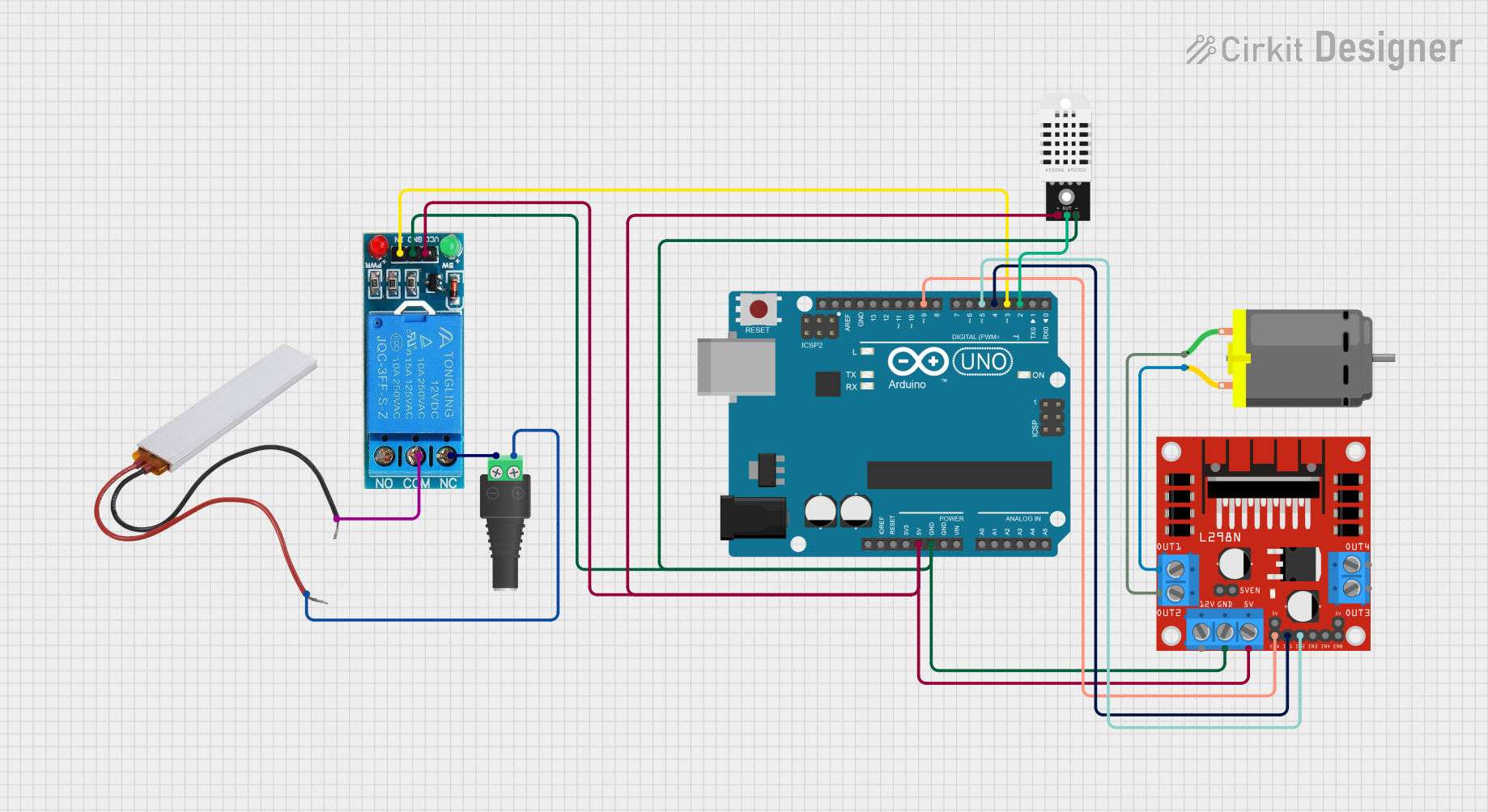
Circuit Documentation
Summary of the Circuit
This circuit is designed to control a DC motor using an Arduino UNO microcontroller and an L298N DC motor driver. It includes a 2.1mm Barrel Jack with Terminal Block for power input, a 12V single-channel relay for controlling power pathways, a PTC for circuit protection, and a DHT22 sensor for measuring temperature and humidity. The Arduino UNO is the central control unit that interfaces with the relay, motor driver, and sensor to manage the motor's operation based on sensor inputs and programmed logic.
Component List
2.1mm Barrel Jack with Terminal Block
- Description: Power connector for the circuit.
- Pins: POS (Positive), NEG (Negative)
12V Single Channel Relay
- Description: Electromechanical switch used for controlling high power devices.
- Pins: NC (Normally Closed), COM (Common), NO (Normally Open), IN (Input), GND (Ground), VCC (Voltage Common Collector)
PTC (Positive Temperature Coefficient)
- Description: A resettable fuse used for overcurrent protection.
- Pins: Neutral, Live
L298N DC Motor Driver
- Description: A module for controlling DC motors.
- Pins: OUT1, OUT2, 12V, GND, 5V, OUT3, OUT4, 5V-ENA-JMP-I, 5V-ENA-JMP-O, +5V-J1, +5V-J2, ENA, IN1, IN2, IN3, IN4, ENB
DC Motor
- Description: An electric motor that runs on direct current electricity.
- Pins: pin 1, pin 2
DHT22
- Description: A sensor for measuring temperature and humidity.
- Pins: VCC, OUT, GND
Arduino UNO
- Description: A microcontroller board based on the ATmega328P.
- Pins: UNUSED, IOREF, Reset, 3.3V, 5V, GND, Vin, A0-A5, SCL, SDA, AREF, D0-D13
Wiring Details
2.1mm Barrel Jack with Terminal Block
- POS connected to PTC (Live)
- NEG connected to 12V Single Channel Relay (NC)
12V Single Channel Relay
- NC connected to 2.1mm Barrel Jack with Terminal Block (NEG)
- COM connected to PTC (Neutral)
- NO not connected
- IN connected to Arduino UNO (D3)
- GND connected to Arduino UNO (GND)
- VCC connected to Arduino UNO (5V)
PTC
- Neutral connected to 12V Single Channel Relay (COM)
- Live connected to 2.1mm Barrel Jack with Terminal Block (POS)
L298N DC Motor Driver
- OUT1 connected to DC Motor (pin 2)
- OUT2 connected to DC Motor (pin 1)
- 12V not connected
- GND connected to Arduino UNO (GND)
- 5V connected to Arduino UNO (5V)
- ENA connected to Arduino UNO (D9)
- IN1 connected to Arduino UNO (D4)
- IN2 connected to Arduino UNO (D5)
DC Motor
- pin 1 connected to L298N DC Motor Driver (OUT2)
- pin 2 connected to L298N DC Motor Driver (OUT1)
DHT22
- VCC connected to Arduino UNO (5V)
- OUT connected to Arduino UNO (D2)
- GND connected to Arduino UNO (GND)
Arduino UNO
- D3 connected to 12V Single Channel Relay (IN)
- GND connected to L298N DC Motor Driver (GND), DHT22 (GND), 12V Single Channel Relay (GND)
- 5V connected to L298N DC Motor Driver (5V), DHT22 (VCC), 12V Single Channel Relay (VCC)
- D9 connected to L298N DC Motor Driver (ENA)
- D5 connected to L298N DC Motor Driver (IN2)
- D4 connected to L298N DC Motor Driver (IN1)
- D2 connected to DHT22 (OUT)
Documented Code
Arduino UNO Code (sketch.ino)
void setup() {
  // put your setup code here, to run once:

}

void loop() {
  // put your main code here, to run repeatedly:

}
Note: The provided code is a template and does not contain any functional logic. It needs to be populated with the specific setup and loop instructions to control the motor and read from the DHT22 sensor.