
12V Battery-Powered Motor Control with Voltage Regulation and Charge Management
View and Edit Project In Cirkit Designer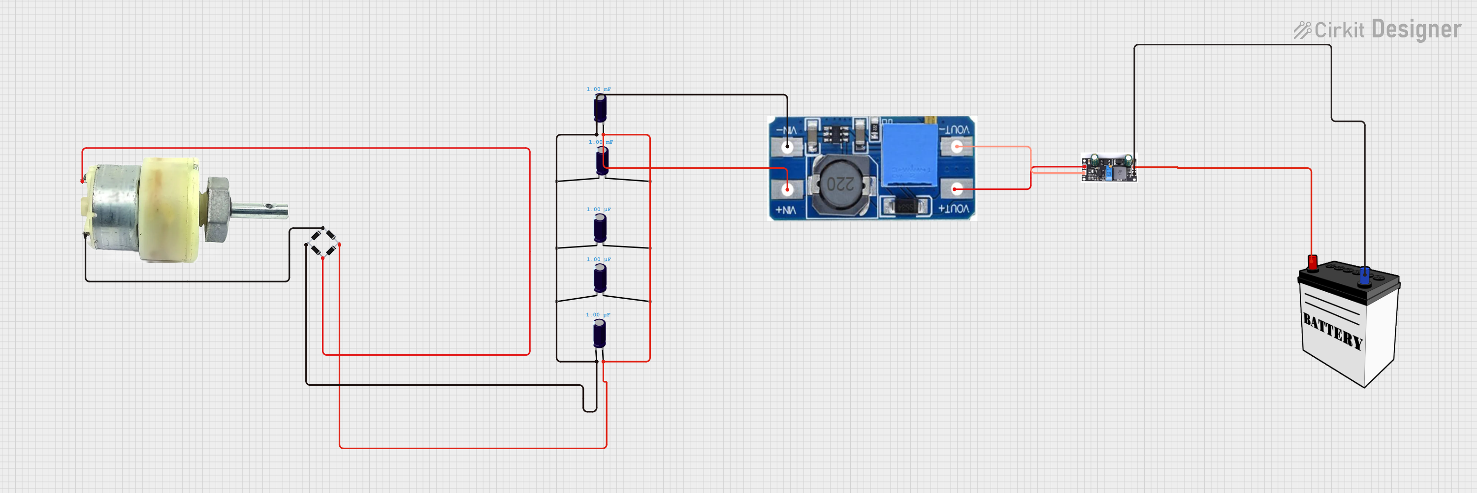
Circuit Documentation
Summary of the Circuit
The circuit in question appears to be a power regulation and motor control system. It includes a 12V geared motor, a bridge rectifier for converting AC to DC, multiple electrolytic capacitors for smoothing voltage fluctuations, a step-up boost power converter to adjust voltage levels, a charge controller for managing power flow to a battery, and a 12V battery for energy storage. The circuit does not include any microcontrollers or embedded code.
Component List
12V Geared Motor
- Description: A motor that operates at 12V and includes a gearbox for increased torque.
- Pins: Terminal 1, Terminal 2
Bridge Rectifier
- Description: A component that converts alternating current (AC) to direct current (DC).
- Pins: Source_in-, Source_out-, Source_out+, Source_in+
Electrolytic Capacitors
- Description: Capacitors used for filtering and smoothing the ripple in power supplies.
- Capacitance: Various values (1µF and 0.001F)
- Pins: -, +
Step Up Boost Power Converter, Adjustable Voltage Regulator
- Description: A device that steps up the input voltage to a higher output voltage.
- Pins: VOUT+, VOUT-, VIN+, VIN-
Charge Controller
- Description: Manages the power going into the battery to prevent overcharging.
- Pins: GND, BAT, Vin
12V Battery
- Description: Stores electrical energy for use by the circuit.
- Pins: VCC, GND
Wiring Details
12V Geared Motor
- Terminal 1 connected to Bridge rectifier (source_in+)
- Terminal 2 connected to Bridge rectifier (Source_in-)
Bridge Rectifier
- Source_in+ connected to 12V Geared Motor (Terminal 1)
- Source_in- connected to 12V Geared Motor (Terminal 2)
- Source_out- connected to Step Up Boost Power Converter (VIN-), Electrolytic Capacitors (-)
- Source_out+ connected to Step Up Boost Power Converter (VIN+), Electrolytic Capacitors (+)
Electrolytic Capacitors
- Capacitors with 1µF capacitance:
- (-) pin connected to Step Up Boost Power Converter (VIN-), Bridge rectifier (source_out-)
- (+) pin connected to Step Up Boost Power Converter (VIN+), Bridge rectifier (source_out+)
- Capacitors with 0.001F capacitance:
- (-) pin connected to Step Up Boost Power Converter (VIN-), Bridge rectifier (source_out-)
- (+) pin connected to Step Up Boost Power Converter (VIN+), Bridge rectifier (source_out+)
Step Up Boost Power Converter, Adjustable Voltage Regulator
- VIN- connected to Bridge rectifier (source_out-), Electrolytic Capacitors (-)
- VIN+ connected to Bridge rectifier (source_out+), Electrolytic Capacitors (+)
- VOUT+ connected to Charge controller (Vin)
- VOUT- connected to Charge controller (GND)
Charge Controller
- GND connected to Step Up Boost Power Converter (VOUT-), 12V Battery (GND)
- BAT connected to 12V Battery (VCC)
- Vin connected to Step Up Boost Power Converter (VOUT+)
12V Battery
- GND connected to Charge controller (GND)
- VCC connected to Charge controller (BAT)
Documented Code
There is no embedded code provided for this circuit. Therefore, this section is not applicable.
This documentation provides an overview of the circuit's components, their connections, and their roles within the system. It should serve as a guide for understanding, maintaining, or further developing the circuit.