
Arduino Mega 2560 Battery-Powered Robotic Vehicle with Reflectance Sensor and Motor Control
View and Edit Project In Cirkit Designer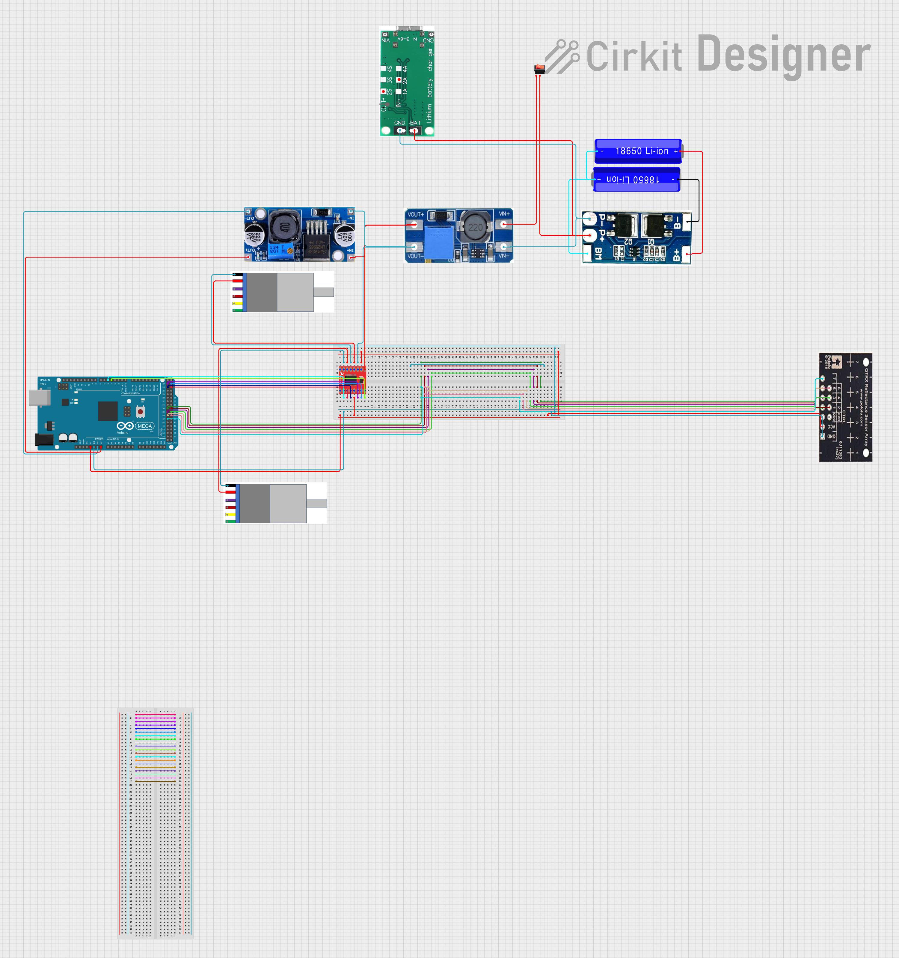
Circuit Documentation
Summary
This document provides a detailed overview of a circuit that includes various components such as a motor driver, gear motors with encoders, a reflectance sensor array, a rocker switch, a lithium battery charging board, a step-up boost power converter, a buck converter, a 2S lithium battery protection board, and an Arduino Mega 2560 microcontroller. The circuit is designed to control motors and read sensor data, powered by a lithium battery setup.
Component List
18650 Li-ion Battery
- Description: Rechargeable lithium-ion battery.
- Pins: -, +
Gear Motor with Integrated Encoder
- Description: Motor with an integrated encoder for precise control.
- Pins: MOTOR -, MOTOR+, Encoder -, Encoder +, Encoder A, Encoder B
QTRX-HD-07RC Reflectance Sensor Array
- Description: Sensor array for detecting reflectance.
- Pins: GND, VCC, EVN, ODD, 1, 2, 3, 4, 5, 6, 7
Rocker Switch
- Description: On/Off switch.
- Pins: output, input
Lithium Battery Charging Board Type-C
- Description: Charging board for lithium batteries with Type-C input.
- Pins: GND, BAT, VIN
Step Up Boost Power Converter, Adjustable Voltage Regulator
- Description: Boost converter for stepping up voltage.
- Pins: VOUT+, VOUT-, VIN+, VIN-
Buck Converter, Adjustable Regulator
- Description: Buck converter for stepping down voltage.
- Pins: OUT-, OUT+, IN-, IN+
2S Lithium Battery Protection Board Module
- Description: Protection board for 2S lithium battery packs.
- Pins: B+, B-, BM, P+, P-
Motor Driver 1A Dual TB6612FNG
- Description: Motor driver for controlling two motors.
- Pins: GND, B01, B02, A02, A01, VCC, VM, PWMA, AIN2, AIN1, STBY, BIN1, BIN2, PWMB
Arduino Mega 2560
- Description: Microcontroller board based on the ATmega2560.
- Pins: IOREF, RESET, 3V3, 5V, GND, VIN, A0-A15, D0-D53, AREF, SDA, SCL
Wiring Details
18650 Li-ion Battery
- - connected to 2S lithium battery protection board module B-
- + connected to 2S lithium battery protection board module BM
Gear Motor with Integrated Encoder (Instance 1)
- MOTOR - connected to Motor Driver 1A Dual TB6612FNG B01
- MOTOR+ connected to Motor Driver 1A Dual TB6612FNG B02
Gear Motor with Integrated Encoder (Instance 2)
- MOTOR - connected to Motor Driver 1A Dual TB6612FNG A02
- MOTOR+ connected to Motor Driver 1A Dual TB6612FNG A01
QTRX-HD-07RC Reflectance Sensor Array
- GND connected to Arduino Mega 2560 GND
- VCC connected to Arduino Mega 2560 5V
- 1 connected to Arduino Mega 2560 D36
- 2 connected to Arduino Mega 2560 D37
- 3 connected to Arduino Mega 2560 D38
- 4 connected to Arduino Mega 2560 D39
- 5 connected to Arduino Mega 2560 D40
- 6 connected to Arduino Mega 2560 D41
- 7 connected to Arduino Mega 2560 D42
Rocker Switch
- input connected to Step Up Boost Power Converter, Adjustable Voltage Regulator VIN+
- output connected to Lithium Battery Charging Board Type-C BAT
Lithium Battery Charging Board Type-C
- GND connected to Step Up Boost Power Converter, Adjustable Voltage Regulator VIN-
- BAT connected to rocker switch output
Step Up Boost Power Converter, Adjustable Voltage Regulator
- VOUT+ connected to Motor Driver 1A Dual TB6612FNG VM
- VOUT- connected to Motor Driver 1A Dual TB6612FNG GND
Buck Converter, Adjustable Regulator
- IN+ connected to Step Up Boost Power Converter, Adjustable Voltage Regulator VOUT+
- IN- connected to Step Up Boost Power Converter, Adjustable Voltage Regulator VOUT-
- OUT+ connected to Arduino Mega 2560 VIN
- OUT- connected to Arduino Mega 2560 GND
2S Lithium Battery Protection Board Module
- B+ connected to 18650 Li-ion Battery +
- B- connected to 18650 Li-ion Battery -
- BM connected to 18650 Li-ion Battery +
- P+ connected to Lithium Battery Charging Board Type-C BAT
- P- connected to Lithium Battery Charging Board Type-C GND
Motor Driver 1A Dual TB6612FNG
- PWMB connected to Arduino Mega 2560 D5 PWM
- B01 connected to Gear Motor with Integrated Encoder MOTOR - (Instance 1)
- B02 connected to Gear Motor with Integrated Encoder MOTOR+ (Instance 1)
- BIN2 connected to Arduino Mega 2560 D25
- BIN1 connected to Arduino Mega 2560 D24
- A02 connected to Gear Motor with Integrated Encoder MOTOR - (Instance 2)
- A01 connected to Gear Motor with Integrated Encoder MOTOR+ (Instance 2)
- AIN1 connected to Arduino Mega 2560 D22
- AIN2 connected to Arduino Mega 2560 D23
- PWMA connected to Arduino Mega 2560 D4 PWM
- STBY connected to Arduino Mega 2560 5V
- VCC connected to Arduino Mega 2560 5V
- GND connected to Step Up Boost Power Converter, Adjustable Voltage Regulator VOUT-
- VM connected to Step Up Boost Power Converter, Adjustable Voltage Regulator VOUT+
Arduino Mega 2560
- D5 PWM connected to Motor Driver 1A Dual TB6612FNG PWMB
- D25 connected to Motor Driver 1A Dual TB6612FNG BIN2
- D24 connected to Motor Driver 1A Dual TB6612FNG BIN1
- D22 connected to Motor Driver 1A Dual TB6612FNG AIN1
- D23 connected to Motor Driver 1A Dual TB6612FNG AIN2
- D4 PWM connected to Motor Driver 1A Dual TB6612FNG PWMA
- 5V connected to Motor Driver 1A Dual TB6612FNG STBY
- 5V connected to QTRX-HD-07RC Reflectance Sensor Array VCC
- 5V connected to Motor Driver 1A Dual TB6612FNG VCC
- GND connected to QTRX-HD-07RC Reflectance Sensor Array GND
- GND connected to Buck Converter, Adjustable Regulator OUT-
- VIN connected to Buck Converter, Adjustable Regulator OUT+
Documented Code
Arduino Mega 2560 Code
void setup() {
  // put your setup code here, to run once:

}

void loop() {
  // put your main code here, to run repeatedly:

}
This concludes the documentation for the circuit. Each component and its connections have been detailed, along with the code for the Arduino Mega 2560 microcontroller.