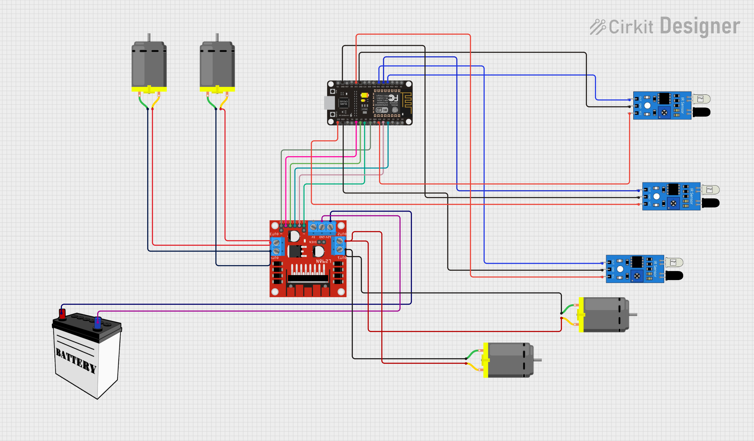
ESP8266 NodeMCU Controlled Multi-Motor System with IR Sensors

Circuit Documentation
Summary
This circuit is designed to control multiple DC motors using an ESP8266 NodeMCU microcontroller and an L298N DC motor driver. The circuit also includes IR sensors for input, which can be used for various sensing applications such as obstacle detection or line tracking. The ESP8266 NodeMCU is responsible for processing the signals from the IR sensors and accordingly controlling the speed and direction of the DC motors through the L298N driver. A 12V battery provides the necessary power for the motors and the motor driver.
Component List
ESP8266 NodeMCU
- Microcontroller module with WiFi capability.
- Pins: D0, D1, D2, D3, D4, 3V3, GND, D5, D6, D7, D8, RX, TX, A0, RSV, SD3, SD2, SD1, CMD, SD0, CLK, EN, RST, VIN.
DC Motor
- Electric motor that converts DC electrical power into mechanical motion.
- Pins: pin 1, pin 2.
L298N DC Motor Driver
- A module that can control up to two DC motors with direction and speed control.
- Pins: OUT1, OUT2, 12V, GND, 5V, OUT3, OUT4, 5V-ENA-JMP-I, 5V-ENA-JMP-O, +5V-J1, +5V-J2, ENA, IN1, IN2, IN3, IN4, ENB.
12V Battery
- Power source for the motors and motor driver.
- Pins: VCC, GND.
IR Sensor
- Sensor that detects infrared light to sense objects or movement.
- Pins: out, gnd, vcc.
Wiring Details
ESP8266 NodeMCU
- D3 connected to L298N IN2.
- D4 connected to L298N IN1.
- 3V3 connected to IR sensor VCC (multiple sensors).
- GND connected to IR sensor GND (multiple sensors) and L298N GND.
- D5 connected to L298N ENB.
- D6 connected to L298N ENA.
- D7 connected to L298N IN3.
- D8 connected to L298N IN4.
- SD3 connected to IR sensor out.
- SD2 connected to IR sensor out.
- SD1 connected to IR sensor out.
DC Motor
- Motor 1 pin 1 connected to L298N OUT4.
- Motor 1 pin 2 connected to L298N OUT3.
- Motor 2 pin 1 connected to L298N OUT1.
- Motor 2 pin 2 connected to L298N OUT2.
L298N DC Motor Driver
- OUT1, OUT2, OUT3, OUT4 connected to corresponding DC Motor pins.
- 12V connected to 12V Battery VCC.
- GND connected to 12V Battery GND.
- IN1, IN2, IN3, IN4 connected to corresponding ESP8266 NodeMCU pins.
- ENA, ENB connected to corresponding ESP8266 NodeMCU pins.
12V Battery
- VCC connected to L298N 12V.
- GND connected to L298N GND.
IR Sensor
- VCC connected to ESP8266 NodeMCU 3V3.
- GND connected to ESP8266 NodeMCU GND.
- Out connected to ESP8266 NodeMCU SD3, SD2, SD1 (one sensor to each pin).
Documented Code
No code has been provided for the microcontroller. The documentation of the code would typically include a description of the functionality, setup, and loop functions, as well as any functions or libraries used to control the motors and read the sensors. Since no code is available, this section cannot be completed.