
DC Motor Control System with BTS7960 Motor Driver and Arcade Buttons
View and Edit Project In Cirkit Designer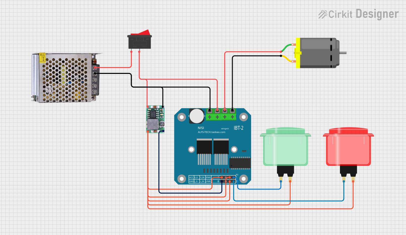
Circuit Documentation
Summary
This document provides a detailed overview of a circuit designed to control a DC motor using a BTS7960 motor driver, powered by a 12V power supply and a Mini-360 DC-DC step-down buck converter. The circuit also includes a rocker switch and two arcade buttons (red and green) for user input.
Component List
BTS7960 Motor Driver
- Description: A high-power motor driver capable of driving large DC motors.
- Pins: Pin 1, Pin 2, Pin 3, Pin 4, Pin 5, Pin 6, Pin 7, Pin 8, Pin 9, Pin 10, Pin 11, Pin 12
POWER SUPPLY 12V 5AMP
- Description: A power supply unit providing 12V DC output at up to 5A.
- Pins: 220V Positive Pole (AC), 220V Negative Pole (AC), GND, GND (DC), 12V-24V Output (DC)
Mini-360 DC-DC Step Down Buck Converter
- Description: A step-down converter to reduce the voltage from the power supply to a suitable level for the motor driver.
- Pins: Input -, Input +, Output +, Output -
Rocker Switch
- Description: A simple on/off switch to control the power to the circuit.
- Pins: 1, 2
DC Motor
- Description: A DC motor to be controlled by the motor driver.
- Pins: pin 1, pin 2
Arcade Button (red)
- Description: A red arcade button for user input.
- Pins: no name yet
Arcade Button (green)
- Description: A green arcade button for user input.
- Pins: no name yet
Wiring Details
BTS7960 Motor Driver
- Pin 1 is connected to Output - of the Mini-360 DC-DC Step Down Buck Converter.
- Pin 3, Pin 5, and Pin 7 are connected to the no name yet pin of the Arcade Button (green).
- Pin 3, Pin 5, and Pin 7 are also connected to the no name yet pin of the Arcade Button (red).
- Pin 4 is connected to the no name yet pin of the Arcade Button (red).
- Pin 8 is connected to the no name yet pin of the Arcade Button (green).
- Pin 9 is connected to pin 2 of the DC Motor.
- Pin 10 is connected to pin 1 of the DC Motor.
- Pin 11 is connected to pin 2 of the Rocker Switch.
- Pin 11 is also connected to Input + of the Mini-360 DC-DC Step Down Buck Converter.
- Pin 12 is connected to GND (DC) of the POWER SUPPLY 12V 5AMP.
- Pin 12 is also connected to Input - of the Mini-360 DC-DC Step Down Buck Converter.
POWER SUPPLY 12V 5AMP
- GND (DC) is connected to Pin 12 of the BTS7960 Motor Driver.
- GND (DC) is also connected to Input - of the Mini-360 DC-DC Step Down Buck Converter.
- 12V-24V Output (DC) is connected to pin 1 of the Rocker Switch.
Mini-360 DC-DC Step Down Buck Converter
- Output - is connected to Pin 1 of the BTS7960 Motor Driver.
- Output + is connected to Pin 3, Pin 5, and Pin 7 of the BTS7960 Motor Driver.
- Output + is also connected to the no name yet pin of the Arcade Button (red).
- Input + is connected to Pin 11 of the BTS7960 Motor Driver.
- Input - is connected to Pin 12 of the BTS7960 Motor Driver.
Rocker Switch
- Pin 1 is connected to 12V-24V Output (DC) of the POWER SUPPLY 12V 5AMP.
- Pin 2 is connected to Pin 11 of the BTS7960 Motor Driver.
DC Motor
- pin 1 is connected to Pin 10 of the BTS7960 Motor Driver.
- pin 2 is connected to Pin 9 of the BTS7960 Motor Driver.
Arcade Button (red)
- no name yet pin is connected to Pin 3, Pin 5, and Pin 7 of the BTS7960 Motor Driver.
- no name yet pin is also connected to Output + of the Mini-360 DC-DC Step Down Buck Converter.
- no name yet pin is connected to Pin 4 of the BTS7960 Motor Driver.
Arcade Button (green)
- no name yet pin is connected to Pin 3, Pin 5, and Pin 7 of the BTS7960 Motor Driver.
- no name yet pin is also connected to Pin 8 of the BTS7960 Motor Driver.
Code
There is no code provided for this circuit.