Arduino UNO-Based Ultrasonic Distance Meter with LCD Display and LED Indicators
Circuit Documentation
Summary
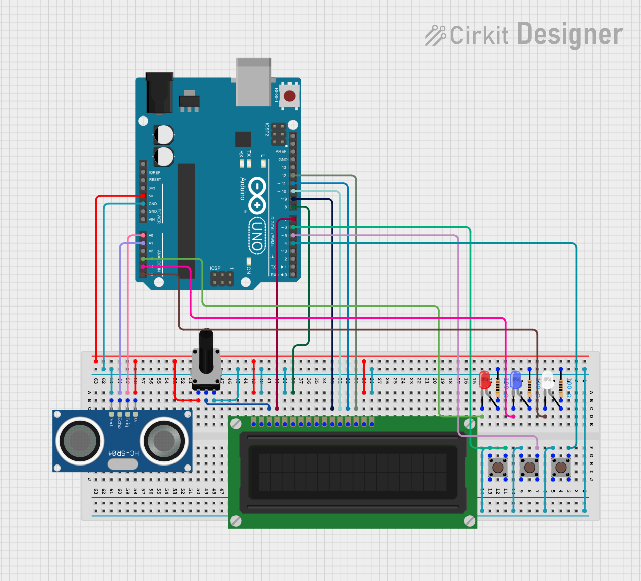
This circuit involves an Arduino UNO microcontroller interfacing with various components including pushbuttons, LEDs, an ultrasonic sensor, an LCD display, and a rotary potentiometer. The circuit is designed to demonstrate basic input and output operations, including reading sensor data, controlling LEDs, and displaying information on an LCD.
Component List
Arduino UNO
- Description: A microcontroller board based on the ATmega328P.
- Pins: UNUSED, IOREF, Reset, 3.3V, 5V, GND, Vin, A0, A1, A2, A3, A4, A5, SCL, SDA, AREF, D13, D12, D11, D10, D9, D8, D7, D6, D5, D4, D3, D2, D1, D0
HC-SR04 Ultrasonic Sensor
- Description: A sensor used to measure distance using ultrasonic waves.
- Pins: VCC, TRIG, ECHO, GND
LCD Display (16 pin)
- Description: A 16-pin LCD display used for showing alphanumeric characters.
- Pins: VSS, VDD, VO, RS, R_W, E, DB0, DB1, DB2, DB3, DB4, DB5, DB6, DB7, A, K
Pushbutton
- Description: A simple pushbutton switch.
- Pins: Pin 3 (out), Pin 4 (out), Pin 1 (in), Pin 2 (in)
Rotary Potentiometer
- Description: A variable resistor used to adjust voltage.
- Pins: leg1, wiper, leg2
- Properties: Resistance: 10,000 Ohms
LED: Two Pin (red)
- Description: A red LED.
- Pins: cathode, anode
LED: Two Pin (blue)
- Description: A blue LED.
- Pins: cathode, anode
LED: Two Pin (white)
- Description: A white LED.
- Pins: cathode, anode
Resistor
- Description: A resistor used to limit current.
- Pins: pin1, pin2
- Properties: Resistance: 100 Ohms
Wiring Details
Arduino UNO
- D4: Connected to Pin 3 (out) and Pin 4 (out) of a Pushbutton.
- D5: Connected to Pin 3 (out) and Pin 4 (out) of a Pushbutton.
- D6: Connected to Pin 3 (out) and Pin 4 (out) of a Pushbutton.
- A0: Connected to TRIG of the HC-SR04 Ultrasonic Sensor.
- A1: Connected to ECHO of the HC-SR04 Ultrasonic Sensor.
- A3: Connected to cathode of the red LED.
- A4: Connected to cathode of the blue LED.
- A5: Connected to cathode of the white LED.
- 5V: Connected to VCC of the HC-SR04 Ultrasonic Sensor, VDD of the LCD Display, leg1 of the Rotary Potentiometer, and A of the LCD Display.
- GND: Connected to GND of the HC-SR04 Ultrasonic Sensor, K of the LCD Display, R_W of the LCD Display, pin1 of three Resistors, and leg2 of the Rotary Potentiometer.
- D7: Connected to RS of the LCD Display.
- D8: Connected to E of the LCD Display.
- D9: Connected to DB4 of the LCD Display.
- D10: Connected to DB5 of the LCD Display.
- D11: Connected to DB6 of the LCD Display.
- D12: Connected to DB7 of the LCD Display.
HC-SR04 Ultrasonic Sensor
- VCC: Connected to 5V of the Arduino UNO.
- TRIG: Connected to A0 of the Arduino UNO.
- ECHO: Connected to A1 of the Arduino UNO.
- GND: Connected to GND of the Arduino UNO.
LCD Display (16 pin)
- VSS: Connected to 5V of the Arduino UNO.
- VDD: Connected to 5V of the Arduino UNO.
- VO: Connected to wiper of the Rotary Potentiometer.
- RS: Connected to D7 of the Arduino UNO.
- R_W: Connected to GND of the Arduino UNO.
- E: Connected to D8 of the Arduino UNO.
- DB4: Connected to D9 of the Arduino UNO.
- DB5: Connected to D10 of the Arduino UNO.
- DB6: Connected to D11 of the Arduino UNO.
- DB7: Connected to D12 of the Arduino UNO.
- A: Connected to 5V of the Arduino UNO.
- K: Connected to GND of the Arduino UNO.
Pushbuttons
- Pin 3 (out) and Pin 4 (out): Connected to D4, D5, and D6 of the Arduino UNO.
- Pin 1 (in) and Pin 2 (in): Connected to pin1 of three Resistors, GND of the Arduino UNO.
Rotary Potentiometer
- leg1: Connected to 5V of the Arduino UNO.
- wiper: Connected to VO of the LCD Display.
- leg2: Connected to GND of the Arduino UNO.
LEDs
- Red LED:
- cathode: Connected to A3 of the Arduino UNO.
- anode: Connected to pin2 of a Resistor.
- Blue LED:
- cathode: Connected to A4 of the Arduino UNO.
- anode: Connected to pin2 of a Resistor.
- White LED:
- cathode: Connected to A5 of the Arduino UNO.
- anode: Connected to pin2 of a Resistor.
Resistors
- pin1: Connected to Pin 1 (in) and Pin 2 (in) of three Pushbuttons, GND of the Arduino UNO.
- pin2: Connected to anode of the red, blue, and white LEDs.
Code Documentation
Arduino UNO Code
void setup() {
  // put your setup code here, to run once:

}

void loop() {
  // put your main code here, to run repeatedly:

}
This code is a basic template for the Arduino UNO. The setup() function is used to initialize any settings or configurations, and the loop() function contains the main code that runs repeatedly. Currently, both functions are empty and can be filled with the desired logic for the circuit.