
Teensy 4.1 Controlled Precision Stepper Motor System with OLED Display and Logic Level Conversion
View and Edit Project In Cirkit Designer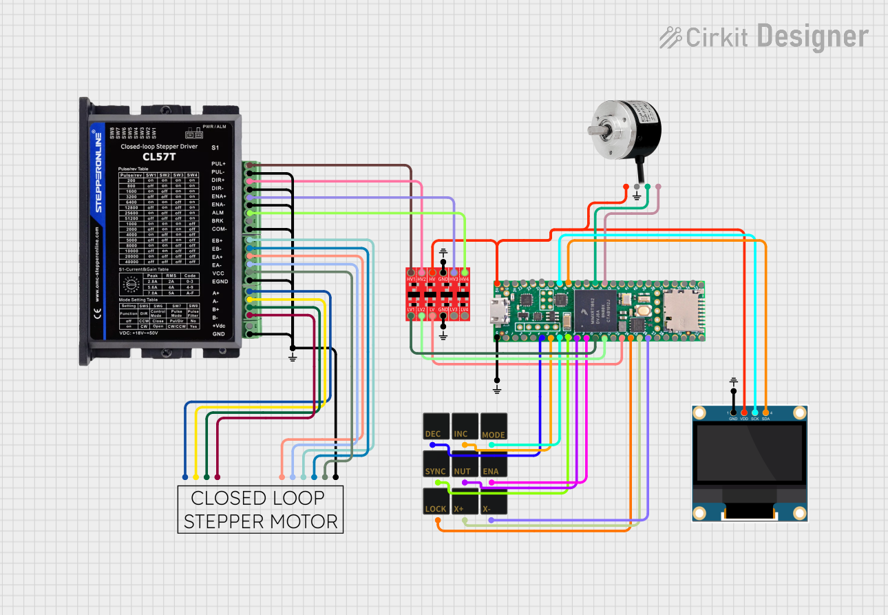
Circuit Documentation
Summary
This circuit is designed to interface various components including a microcontroller (Teensy 4.1), a bi-directional logic level converter, an OLED display, an optical rotary encoder, a keypad for a Teensy ELS (Electronic Lead Screw), and a closed-loop stepper system consisting of a stepper motor and a stepper driver (Stepperonline CL57T). The circuit facilitates communication between the microcontroller and the peripherals, processes user inputs from the keypad, displays information on the OLED, and controls the stepper motor through the driver.
Component List
Bi-Directional Logic Level Converter
- Description: A device that safely steps down 5V signals to 3.3V and steps up 3.3V to 5V simultaneously.
- Pins: HV1, HV2, HV, GND, HV3, HV4, LV1, LV2, LV, LV3, LV4
Small GND
- Description: A ground reference point for the circuit.
- Pins: GND
Teensy 4.1
- Description: A high-performance microcontroller board capable of digital and analog I/O, PWM, and more.
- Pins: Ground, 0-33, 3v, 5V/Input, 3V, 23-41
0.96" OLED
- Description: A small display for visual output from the microcontroller.
- Pins: GND, VDD, SCK, SDA
Teensy ELS Keypad
- Description: A keypad interface for the Teensy Electronic Lead Screw, providing user input capabilities.
- Pins: Decrease Pitch, Increase Pitch, Feed/Thread Mode Toggle, Set thread Start/Stop point, Activate Automatic Half-nut, Enable Toggle, Lock Toggle (Hold), Jog+, Jog-
Optical Rotary Encoder
- Description: A sensor that provides feedback on the position or motion of a rotating object.
- Pins: VIN, GND, A, B
Stepperonline CL57T Closed Loop Stepper Driver
- Description: A driver for controlling a closed-loop stepper motor.
- Pins: PUL+, PUL-, DIR+, DIR-, ENA+, ENA-, ALM, BRK, COM-, EB+, EB-, EA+, EA-, VCC, A+, A-, B+, B-, +VDC, GND, EGND
Closed Loop Stepper
- Description: A stepper motor with feedback for precise control of motion.
- Pins: B-, A-, B+, A+, GND, VCC, EB-, EB+, EA-, EA+
Wiring Details
Bi-Directional Logic Level Converter
- HV1 connected to Stepper Driver PUL+
- HV2 connected to Stepper Driver DIR+
- HV connected to 5V/Input from Teensy 4.1 and VDD from OLED
- GND connected to Small GND
- HV3 connected to Stepper Driver ENA+
- HV4 connected to Stepper Driver ALM
- LV1 connected to Teensy 4.1 pin 10
- LV2 connected to Teensy 4.1 pin 11
- LV connected to Teensy 4.1 pin 3v
Small GND
- GND connected to various components as a common ground reference.
Teensy 4.1
- Ground connected to Small GND
- Pin 4 connected to Keypad Decrease Pitch
- Pin 5 connected to Keypad Increase Pitch
- Pin 6 connected to Keypad Feed/Thread Mode Toggle
- Pin 7 connected to Keypad Set thread Start/Stop point
- Pin 8 connected to Keypad Activate Automatic Half-nut
- Pin 9 connected to Keypad Enable Toggle
- Pin 10 connected to Logic Level Converter LV1
- Pin 11 connected to Logic Level Converter LV2
- Pin 3v connected to Logic Level Converter LV
- Pin 5V/Input connected to OLED VDD, Rotary Encoder VIN, and Logic Level Converter HV
- Pin 19 connected to OLED SCK
- Pin 18 connected to OLED SDA
- Pin 15 connected to Rotary Encoder A
- Pin 14 connected to Rotary Encoder B
0.96" OLED
- GND connected to Small GND
- VDD connected to 5V/Input from Teensy 4.1
- SCK connected to Teensy 4.1 pin 19
- SDA connected to Teensy 4.1 pin 18
Teensy ELS Keypad
- Decrease Pitch connected to Teensy 4.1 pin 4
- Increase Pitch connected to Teensy 4.1 pin 5
- Feed/Thread Mode Toggle connected to Teensy 4.1 pin 6
- Set thread Start/Stop point connected to Teensy 4.1 pin 7
- Activate Automatic Half-nut connected to Teensy 4.1 pin 8
- Enable Toggle connected to Teensy 4.1 pin 9
- Lock Toggle (Hold) connected to Teensy 4.1 pin 24
- Jog+ connected to Teensy 4.1 pin 25
- Jog- connected to Teensy 4.1 pin 26
Optical Rotary Encoder
- VIN connected to 5V/Input from Teensy 4.1
- GND connected to Small GND
- A connected to Teensy 4.1 pin 15
- B connected to Teensy 4.1 pin 14
Stepperonline CL57T Closed Loop Stepper Driver
- PUL+ connected to Logic Level Converter HV1
- DIR+ connected to Logic Level Converter HV2
- ENA+ connected to Logic Level Converter HV3
- ALM connected to Logic Level Converter HV4
- PUL-, DIR-, ENA-, COM-, GND, EGND connected to Small GND
- EB+ connected to Closed Loop Stepper EB+
- EB- connected to Closed Loop Stepper EB-
- EA+ connected to Closed Loop Stepper EA+
- EA- connected to Closed Loop Stepper EA-
- VCC connected to Closed Loop Stepper VCC
- A+ connected to Closed Loop Stepper A+
- A- connected to Closed Loop Stepper A-
- B+ connected to Closed Loop Stepper B+
- B- connected to Closed Loop Stepper B-
Closed Loop Stepper
- B-, A-, B+, A+ connected to corresponding pins on Stepper Driver
- GND connected to Small GND
- VCC connected to Stepper Driver VCC
- EB-, EB+ connected to corresponding pins on Stepper Driver
- EA-, EA+ connected to corresponding pins on Stepper Driver
Documented Code
No code has been provided for the microcontroller(s) in this circuit. Typically, the code would be documented here, including setup routines, main loop, interrupt service routines, and any libraries or external modules used. The code would be responsible for initializing the hardware components, handling the logic for input processing from the keypad, controlling the OLED display, and managing the stepper motor's operation through the driver.