
Circuit Documentation
Summary of the Circuit
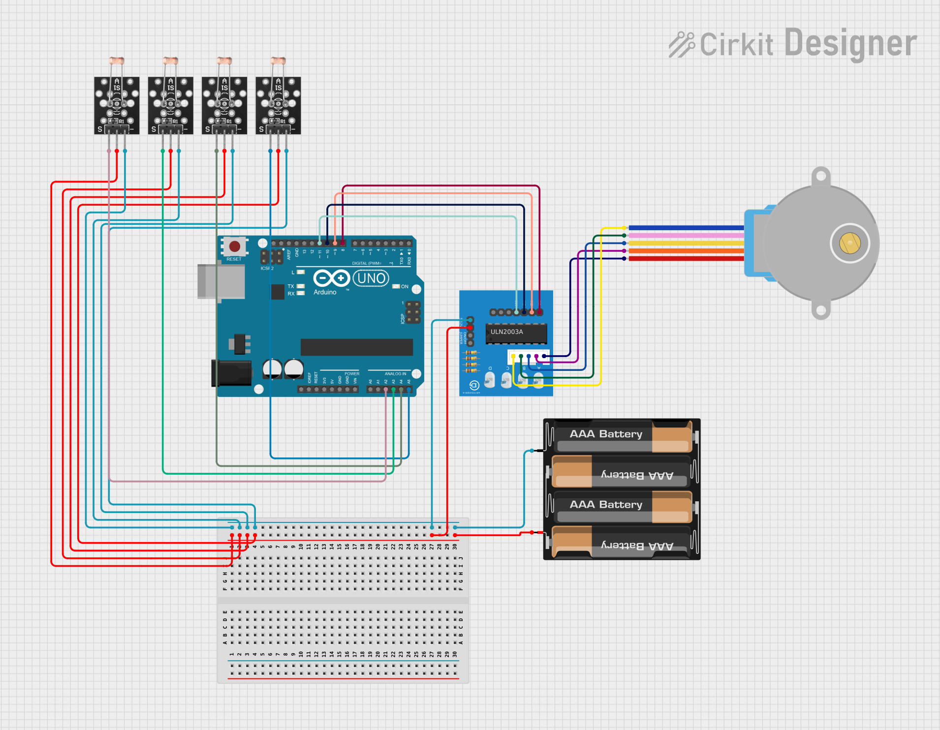
This circuit consists of an Arduino UNO microcontroller, a 4 x AAA battery mount, a 28BYJ-48 stepper motor with a ULN2003A breakout board, and four KY-018 LDR photoresistors. The Arduino UNO is used as the central processing unit to control the stepper motor via the ULN2003A driver and to read analog signals from the LDR photoresistors. The battery mount provides power to the circuit. The stepper motor is used for precise rotational movement, and the LDR photoresistors are used to detect light intensity.
Component List
Arduino UNO
- Microcontroller board based on the ATmega328P
- Digital I/O Pins: 14 (of which 6 provide PWM output)
- Analog Input Pins: 6
- Operating Voltage: 5V
4 x AAA Battery Mount
- Battery holder for four AAA batteries
- Provides power to the circuit
28BYJ-48 Stepper Motor
- Small and inexpensive stepper motor
- Operating Voltage: 5V
- Step Angle: 5.625°/64
ULN2003A Breakout Board
- Stepper motor driver board for the 28BYJ-48 motor
- Contains a ULN2003A transistor array
KY-018 LDR Photo Resistor (x4)
- Light-dependent resistor (LDR) module
- Used to detect the presence and intensity of light
Wiring Details
Arduino UNO
- A2 connected to Signal of LDR Photo Resistor 1
- A3 connected to Signal of LDR Photo Resistor 2
- A4 connected to Signal of LDR Photo Resistor 3
- A5 connected to Signal of LDR Photo Resistor 4
- D8 connected to In 1 of ULN2003A breakout board
- D9 connected to In 2 of ULN2003A breakout board
- D10 connected to In 3 of ULN2003A breakout board
- D11 connected to In 4 of ULN2003A breakout board
4 x AAA Battery Mount
- "+" connected to +5V of ULN2003A breakout board and VCC of all LDR Photo Resistors
- "-" connected to 0V of ULN2003A breakout board and Ground of all LDR Photo Resistors
28BYJ-48 Stepper Motor
- BLUE connected to BLUE wire of ULN2003A breakout board
- PINK connected to PINK wire of ULN2003A breakout board
- YELLOW connected to YELLOW wire of ULN2003A breakout board
- ORANGE connected to ORANGE wire of ULN2003A breakout board
- RED (common wire) connected to RED wire of ULN2003A breakout board
ULN2003A Breakout Board
- In 1 connected to D8 of Arduino UNO
- In 2 connected to D9 of Arduino UNO
- In 3 connected to D10 of Arduino UNO
- In 4 connected to D11 of Arduino UNO
- +5V connected to "+" of 4 x AAA Battery Mount
- 0V connected to "-" of 4 x AAA Battery Mount
- Motor wires connected to corresponding wires of 28BYJ-48 Stepper Motor
KY-018 LDR Photo Resistor (x4)
- Signal connected to A2, A3, A4, A5 of Arduino UNO (respectively for each LDR)
- VCC connected to "+" of 4 x AAA Battery Mount
- Ground connected to "-" of 4 x AAA Battery Mount
Documented Code
Arduino UNO Code (sketch.ino)
void setup() {
  // put your setup code here, to run once:

}

void loop() {
  // put your main code here, to run repeatedly:

}
Additional Notes (documentation.txt)
No additional documentation provided for the code.