
Smart Home Monitoring System with NodeMCU ESP8266 and Multiple Sensors
View and Edit Project In Cirkit Designer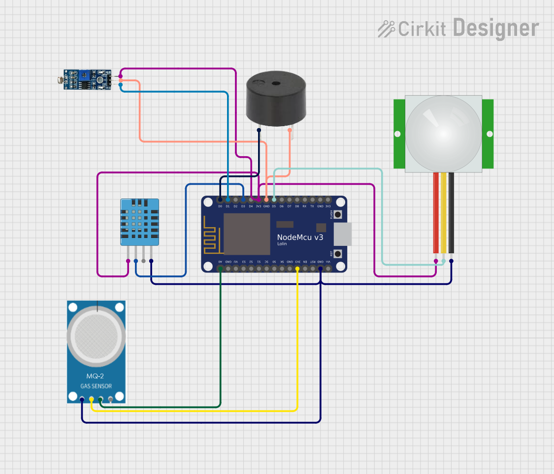
Circuit Documentation
Summary
This document provides a detailed overview of a circuit that includes a NodeMCU V3 ESP8266 microcontroller, a buzzer, a PIR sensor, a DHT11 humidity and temperature sensor, an LDR module, and an MQ-2 gas sensor. The circuit is designed to monitor environmental conditions and trigger alerts based on sensor inputs.
Component List
NodeMCU V3 ESP8266
- Description: A microcontroller with built-in Wi-Fi capabilities, used for controlling the circuit and processing sensor data.
- Pins: A0, GND, VU, S3, S2, S1, SC, S0, SK, 3V3, EN, RST, Vin, D0, D1, D2, D3, D4, D5, D6, D7, D8, RX, TX
Buzzer
- Description: An audio signaling device used to produce sound alerts.
- Pins: PIN, GND
PIR Sensor
- Description: A passive infrared sensor used to detect motion.
- Pins: VDD, SIG, GND
DHT11 Humidity and Temperature Sensor
- Description: A sensor used to measure humidity and temperature.
- Pins: VDD, DATA, NULL, GND
LDR Module 3 Pin
- Description: A light-dependent resistor module used to detect light intensity.
- Pins: VCC, GND, DO
MQ-2 Gas Sensor
- Description: A sensor used to detect gas levels.
- Pins: GND, VCC, ANALOG, Digital
Wiring Details
NodeMCU V3 ESP8266
- A0: Connected to MQ-2 (ANALOG)
- GND: Connected to MQ-2 (GND), PIR Sensor (GND), DHT11 (GND), Buzzer (GND), LDR Module (GND)
- 3V3: Connected to MQ-2 (VCC), LDR Module (VCC), PIR Sensor (VDD), DHT11 (VDD)
- D0: Connected to Buzzer (PIN)
- D1: Connected to LDR Module (DO)
- D3: Connected to DHT11 (DATA)
- D5: Connected to PIR Sensor (SIG)
Buzzer
- PIN: Connected to NodeMCU V3 ESP8266 (D0)
- GND: Connected to NodeMCU V3 ESP8266 (GND)
PIR Sensor
- VDD: Connected to NodeMCU V3 ESP8266 (3V3)
- SIG: Connected to NodeMCU V3 ESP8266 (D5)
- GND: Connected to NodeMCU V3 ESP8266 (GND)
DHT11 Humidity and Temperature Sensor
- VDD: Connected to NodeMCU V3 ESP8266 (3V3)
- DATA: Connected to NodeMCU V3 ESP8266 (D3)
- GND: Connected to NodeMCU V3 ESP8266 (GND)
LDR Module 3 Pin
- VCC: Connected to NodeMCU V3 ESP8266 (3V3)
- GND: Connected to NodeMCU V3 ESP8266 (GND)
- DO: Connected to NodeMCU V3 ESP8266 (D1)
MQ-2 Gas Sensor
- GND: Connected to NodeMCU V3 ESP8266 (GND)
- VCC: Connected to NodeMCU V3 ESP8266 (3V3)
- ANALOG: Connected to NodeMCU V3 ESP8266 (A0)
Code
No code is provided for this circuit.