
NodeMCU ESP8266 Controlled Drone with TFT Display and nRF24L01 Communication
View and Edit Project In Cirkit Designer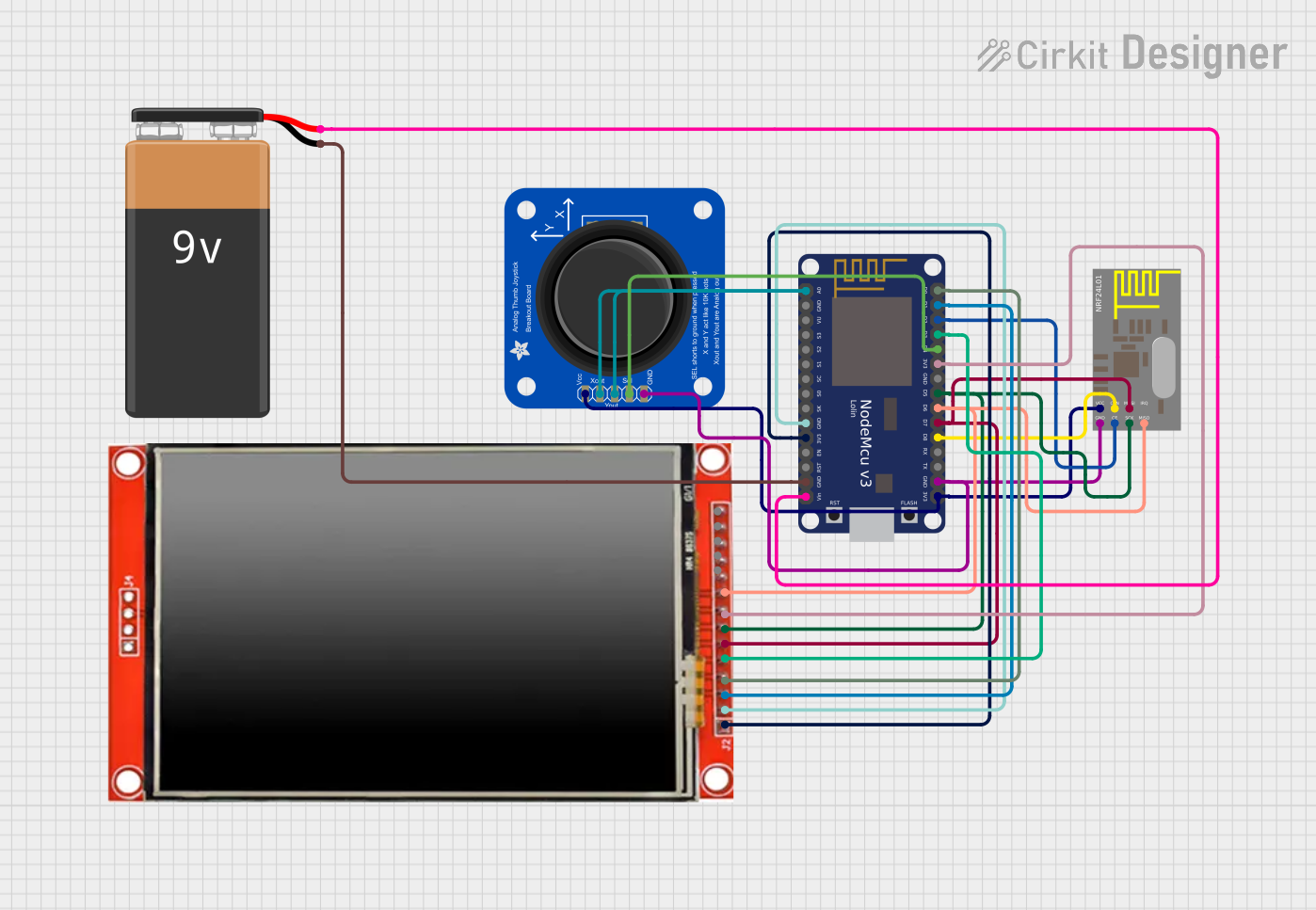
Circuit Documentation
Summary
This circuit integrates a NodeMCU V3 ESP8266 microcontroller with a variety of peripherals including an LCD TFT screen (ILI9488 HD), an nRF24L01 wireless communication module, an Adafruit Analog 2-Axis Joystick, and a 9V Battery for power. The NodeMCU is responsible for interfacing with the joystick and the LCD screen, as well as communicating wirelessly using the nRF24L01 module. The circuit is designed to capture joystick inputs, process them, and transmit control signals wirelessly, potentially for applications such as remote-controlled devices or drones.
Component List
NodeMCU V3 ESP8266
- Microcontroller with WiFi capability
- Pins: A0, GND, VU, S3, S2, S1, SC, S0, SK, 3V3, EN, RST, Vin, D0, D1, D2, D3, D4, D5, D6, D7, D8, RX, TX
LCD TFT screen ILI9488 HD
- High-definition LCD screen for visual output
- Pins: PEN, TDO, TDI, VCC (3.3~5V), GND, CS, RST, D/C, SDI(MOSI), SCK, BL, SDO(MISO), TCS, TCK
nRF24L01
- Wireless communication module for transmitting and receiving data
- Pins: GND, VCC, CE, CSN, SCK, MOSI, MISO, IRQ
Adafruit Analog 2-Axis Joystick
- Analog input device for capturing user movements
- Pins: VCC, XOUT, YOUT, SWITCH, GND
9V Battery
- Power source for the circuit
- Pins: -, +
Wiring Details
NodeMCU V3 ESP8266
- A0 connected to Joystick XOUT and YOUT
- GND connected to LCD GND, nRF24L01 GND, Joystick GND, and Battery -
- 3V3 connected to LCD VCC (3.3~5V), nRF24L01 VCC, and Joystick VCC
- Vin connected to Battery +
- D0 connected to LCD RST
- D1 connected to LCD CS
- D2 connected to nRF24L01 CE
- D3 connected to LCD D/C
- D4 connected to Joystick SWITCH
- D5 connected to LCD SCK and nRF24L01 SCK
- D6 connected to LCD SDO(MISO) and nRF24L01 MISO
- D7 connected to LCD SDI(MOSI) and nRF24L01 MOSI
- D8 connected to nRF24L01 CSN
LCD TFT screen ILI9488 HD
- GND connected to NodeMCU GND
- VCC (3.3~5V) connected to NodeMCU 3V3
- RST connected to NodeMCU D0
- CS connected to NodeMCU D1
- D/C connected to NodeMCU D3
- SCK connected to NodeMCU D5
- SDO(MISO) connected to NodeMCU D6
- SDI(MOSI) connected to NodeMCU D7
- BL connected to NodeMCU 3V3 for backlight control
nRF24L01
- GND connected to NodeMCU GND
- VCC connected to NodeMCU 3V3
- CE connected to NodeMCU D2
- CSN connected to NodeMCU D8
- SCK connected to NodeMCU D5
- MOSI connected to NodeMCU D7
- MISO connected to NodeMCU D6
Adafruit Analog 2-Axis Joystick
- VCC connected to NodeMCU 3V3
- XOUT and YOUT connected to NodeMCU A0
- SWITCH connected to NodeMCU D4
- GND connected to NodeMCU GND
9V Battery
-
- (negative) connected to NodeMCU GND
-
- (positive) connected to NodeMCU Vin
Documented Code
#include <SPI.h>
#include <nRF24L01.h>
#include <RF24.h>
#include <Adafruit_GFX.h>
#include <Adafruit_ILI9488.h>
#include <Servo.h> // Include the Servo library to control ESCs

#define TFT_CS   D1
#define TFT_RST  D0
#define TFT_DC   D9 // Changed from D3 to D9 to avoid conflict

Adafruit_ILI9488 tft = Adafruit_ILI9488(TFT_CS, TFT_DC, TFT_RST);

RF24 radio(D2, D8); // CE, CSN
const byte address[5] = "00001";

struct Data_Package {
  int throttle;
  int yaw;
  int pitch;
  int roll;
};

Data_Package data;

// Create Servo objects to control the ESCs
Servo esc1;
Servo esc2;
Servo esc3;
Servo esc4;

void setup() {
  Serial.begin(9600);
  radio.begin();
  radio.openReadingPipe(0, address);
  radio.setPALevel(RF24_PA_MIN);
  radio.startListening();

  // Attach the ESCs to the appropriate pins
  esc1.attach(D3); // Connect ESC1 signal wire to D3
  esc2.attach(D4); // Connect ESC2 signal wire to D4
  esc3.attach(D5); // Connect ESC3 signal wire to D5
  esc4.attach(D6); // Connect ESC4 signal wire to D6

  // Initialize ESCs with a low throttle value
  esc1.writeMicroseconds(1000);
  esc2.writeMicroseconds(1000);
  esc3.writeMicroseconds(1000);
  esc4.writeMicroseconds(1000);

  delay(2000); // Wait for ESCs to initialize

  // Initialize the TFT screen
  tft.begin();
  tft.setRotation(1);
  tft.fillScreen(ILI9488_BLACK);
}

void loop() {
  if (radio.available()) {
    radio.read(&data, sizeof(Data_Package));

    int throttle = map(data.throttle, 0, 1023, 1000, 2000); // Map throttle to ESC range
    int yaw = map(data.yaw, 0, 1023, 1000, 2000); // Map yaw to ESC range
    int pitch = map(data.pitch, 0, 1023, 1000, 2000); // Map pitch to ESC range
    int roll = map(data.roll, 0, 1023, 1000, 2000); // Map roll to ESC range

    Serial.print("Throttle: ");
    Serial.print(throttle);
    Serial.print(" Yaw: ");
    Serial.print(yaw);
    Serial.print(" Pitch: ");
    Serial.print(pitch);
    Serial.print(" Roll: ");
    Serial.println(roll);

    // Example control logic for motors
    esc1.writeMicroseconds(throttle + pitch + roll);
    esc2.writeMicroseconds(throttle + pitch - roll);
    esc3.writeMicroseconds(throttle - pitch + roll);
    esc4.writeMicroseconds(throttle - pitch - roll);

    // Add additional control logic for yaw if needed
  }

  // Code to receive and display live visuals from the drone
  // This part will depend on how the video data is transmitted
  // and the specific library used for the LCD screen.
  // For example, you might use a separate RF module for video transmission
  // and decode the video data to display on the TFT screen.
}
This code initializes and runs the main functions of the NodeMCU V3 ESP8266 microcontroller. It includes libraries for SPI communication, the nRF24L01 module, graphics for the ILI9488 TFT screen, and servo control. The setup function initializes serial communication, the radio module, and the TFT screen, and attaches the ESCs (Electronic Speed Controllers) to their respective pins. The loop function checks for incoming data from the radio module, processes it, and updates the ESCs accordingly. It also includes a placeholder for video data processing and display on the TFT screen.