
Arduino and ESP32-Based Smart Home Automation System with Stepper Motor and LCD Display
View and Edit Project In Cirkit Designer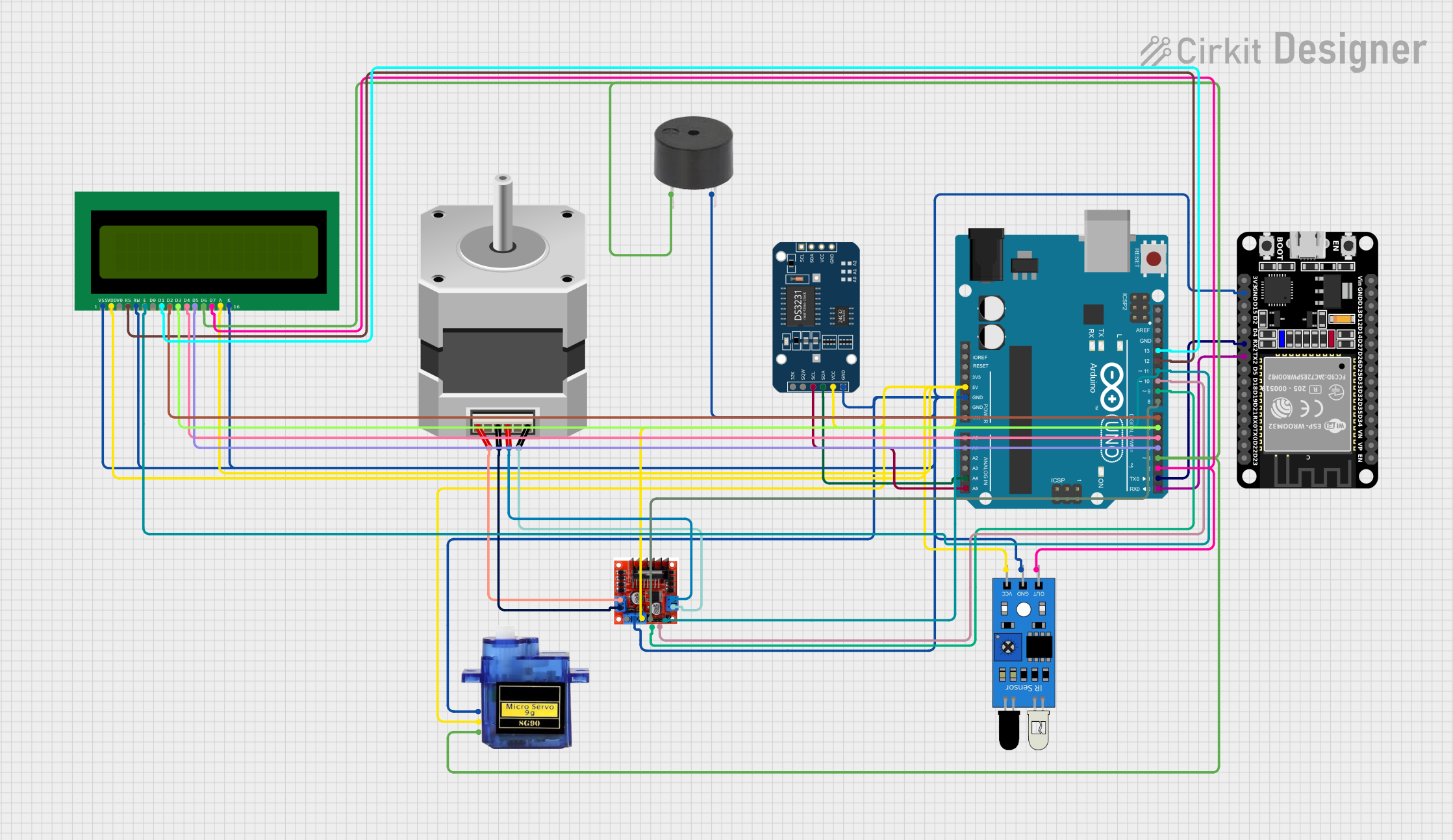
Circuit Documentation
Summary
This document provides a detailed overview of a circuit that includes an Arduino UNO, an ESP32, a DS3231 RTC module, an L298N motor driver, a stepper motor, a micro servo, an IR sensor, a buzzer, and a 16x2 LCD display. The circuit is designed to interface these components for various functionalities, including motor control, timekeeping, and display output.
Component List
Arduino UNO
- Description: A microcontroller board based on the ATmega328P.
- Pins: UNUSED, IOREF, Reset, 3.3V, 5V, GND, Vin, A0, A1, A2, A3, A4, A5, SCL, SDA, AREF, D13, D12, D11, D10, D9, D8, D7, D6, D5, D4, D3, D2, D1, D0
ESP32 (30 pin)
- Description: A low-cost, low-power system on a chip microcontroller with integrated Wi-Fi and dual-mode Bluetooth.
- Pins: EN, VP, VN, D34, D35, D32, D33, D25, D26, D27, D14, D12, D13, GND, Vin, D23, D22, TX0, RX0, D21, D19, D18, D5, TX2, RX2, D4, D2, D15, 3V3
DS3231 RTC
- Description: A low-cost, extremely accurate I2C real-time clock (RTC) with an integrated temperature-compensated crystal oscillator (TCXO) and crystal.
- Pins: 32K, SQW, SCL, SDA, VCC, GND
L298N Motor Driver Controller Board Module Stepper Motor
- Description: A dual H-Bridge motor driver module for controlling DC and stepper motors.
- Pins: Output A, +12v Power, +5v Power, Ground, Output B, Input 4, Input 3, Input 2, Input 1
Stepper Motor (Bipolar)
- Description: A type of stepper motor with two coils and four wires.
- Pins: D, B, C, A
Micro servo 9G
- Description: A small and lightweight servo motor.
- Pins: GND, +5V, PWM
IR Sensor
- Description: An infrared sensor used for detecting objects.
- Pins: out, gnd, vcc
Buzzer
- Description: An electronic device that produces a sound.
- Pins: PIN, GND
16X2 LCD
- Description: A 16x2 character LCD display.
- Pins: VSS, VDD, V0, RS, RW, E, D1, D0, D2, D3, D4, D6, D5, D7, A, K
Wiring Details
Arduino UNO
5V connected to:
- 16X2 LCD (VDD, A)
- L298N Motor Driver (+5v Power)
- DS3231 RTC (VCC)
- Micro servo 9G (+5V)
- IR Sensor (vcc)
GND connected to:
- 16X2 LCD (VSS, K, RW)
- L298N Motor Driver (Ground)
- DS3231 RTC (GND)
- ESP32 (GND)
- Buzzer (GND)
- Micro servo 9G (GND)
- IR Sensor (gnd)
A4 connected to:
- DS3231 RTC (SDA)
A5 connected to:
- DS3231 RTC (SCL)
D13 connected to:
- 16X2 LCD (D1)
D12 connected to:
- 16X2 LCD (RS)
D11 connected to:
- 16X2 LCD (E)
- L298N Motor Driver (Input 4)
D10 connected to:
- L298N Motor Driver (Input 3)
D9 connected to:
- L298N Motor Driver (Input 2)
D8 connected to:
- L298N Motor Driver (Input 1)
D7 connected to:
- 16X2 LCD (D2)
D6 connected to:
- 16X2 LCD (D3)
D5 connected to:
- 16X2 LCD (D4)
D4 connected to:
- 16X2 LCD (D5)
D3 connected to:
- 16X2 LCD (D6)
- Buzzer (PIN)
- Micro servo 9G (PWM)
D2 connected to:
- 16X2 LCD (D7)
- IR Sensor (out)
D1 connected to:
- ESP32 (RX2)
D0 connected to:
- ESP32 (TX2)
ESP32
GND connected to:
- Arduino UNO (GND)
RX2 connected to:
- Arduino UNO (D1)
TX2 connected to:
- Arduino UNO (D0)
DS3231 RTC
VCC connected to:
- Arduino UNO (5V)
GND connected to:
- Arduino UNO (GND)
SDA connected to:
- Arduino UNO (A4)
SCL connected to:
- Arduino UNO (A5)
L298N Motor Driver Controller Board Module Stepper Motor
+5v Power connected to:
- Arduino UNO (5V)
Ground connected to:
- Arduino UNO (GND)
Input 4 connected to:
- Arduino UNO (D11)
Input 3 connected to:
- Arduino UNO (D10)
Input 2 connected to:
- Arduino UNO (D9)
Input 1 connected to:
- Arduino UNO (D8)
Output A connected to:
- Stepper Motor (A, C)
Output B connected to:
- Stepper Motor (D, B)
Stepper Motor (Bipolar)
A connected to:
- L298N Motor Driver (Output A)
B connected to:
- L298N Motor Driver (Output B)
C connected to:
- L298N Motor Driver (Output A)
D connected to:
- L298N Motor Driver (Output B)
Micro servo 9G
+5V connected to:
- Arduino UNO (5V)
GND connected to:
- Arduino UNO (GND)
PWM connected to:
- Arduino UNO (D3)
IR Sensor
vcc connected to:
- Arduino UNO (5V)
gnd connected to:
- Arduino UNO (GND)
out connected to:
- Arduino UNO (D2)
Buzzer
PIN connected to:
- Arduino UNO (D3)
GND connected to:
- Arduino UNO (GND)
16X2 LCD
VDD connected to:
- Arduino UNO (5V)
A connected to:
- Arduino UNO (5V)
VSS connected to:
- Arduino UNO (GND)
K connected to:
- Arduino UNO (GND)
RW connected to:
- Arduino UNO (GND)
D1 connected to:
- Arduino UNO (D13)
RS connected to:
- Arduino UNO (D12)
E connected to:
- Arduino UNO (D11)
- L298N Motor Driver (Input 4)
D2 connected to:
- Arduino UNO (D7)
D3 connected to:
- Arduino UNO (D6)
D4 connected to:
- Arduino UNO (D5)
D5 connected to:
- Arduino UNO (D4)
D6 connected to:
- Arduino UNO (D3)
- Buzzer (PIN)
- Micro servo 9G (PWM)
D7 connected to:
- Arduino UNO (D2)
- IR Sensor (out)
Documented Code
Arduino UNO Code
void setup() {
  // put your setup code here, to run once:

}

void loop() {
  // put your main code here, to run repeatedly:

}
Additional Documentation
No additional documentation provided.