
Arduino Mega 2560-Based Smart Home Automation System with Temperature, Humidity, and Motion Sensors
View and Edit Project In Cirkit Designer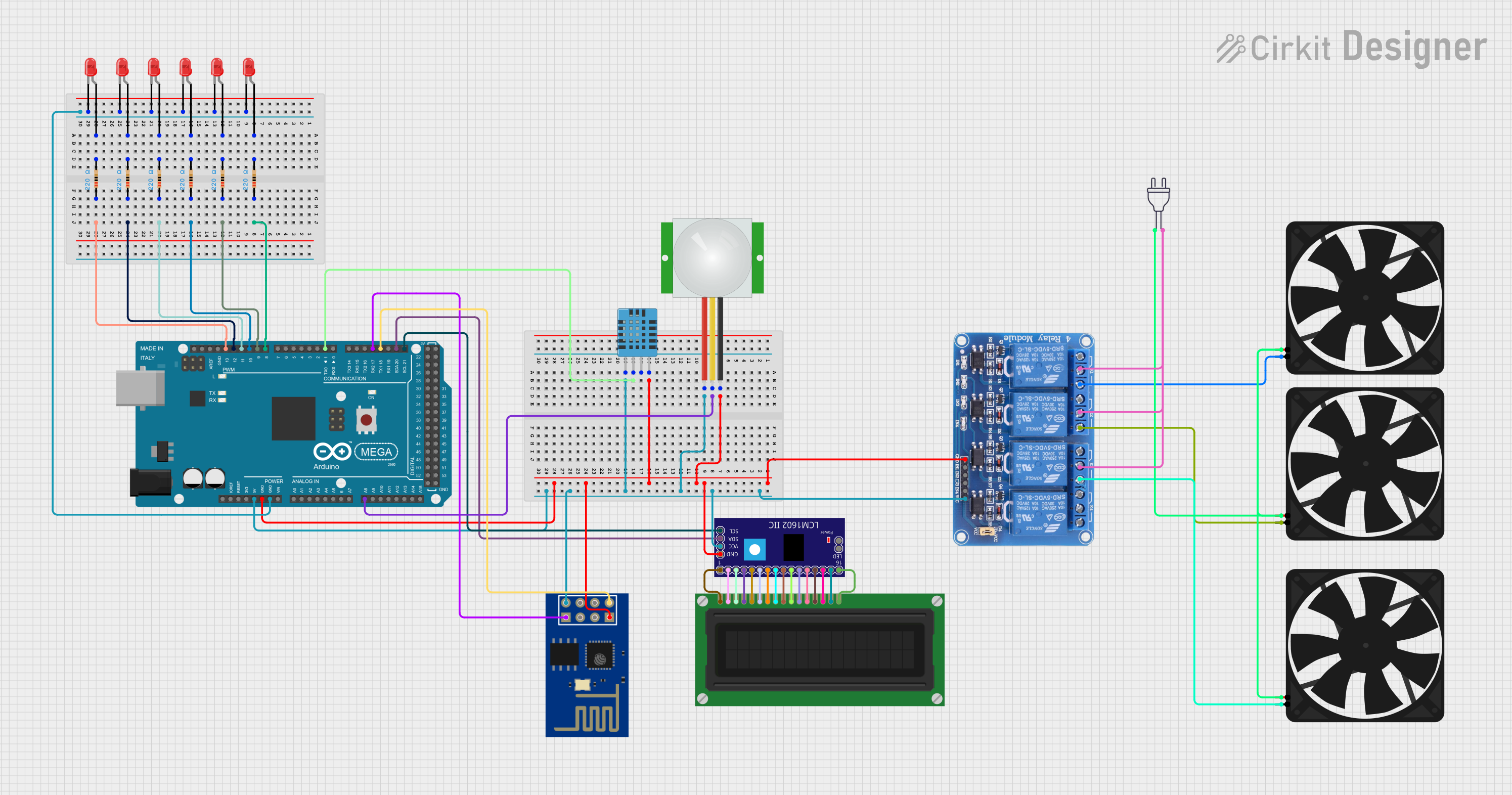
Circuit Documentation
Summary
This circuit is designed to interface various sensors and actuators with an Arduino Mega 2560 microcontroller. The components include a DHT11 humidity and temperature sensor, a PIR sensor, multiple LEDs, resistors, a relay module, fans, an LCD display, and an ESP-01 module. The Arduino Mega 2560 controls the components and executes a predefined pattern of operations.
Component List
DHT11 Humidity and Temperature Sensor
- Pins: VDD, DATA, NULL, GND
- Description: Measures humidity and temperature.
PIR Sensor
- Pins: VDD, SIG, GND
- Description: Detects motion.
Fan
- Pins: GND, 5V
- Description: Provides cooling.
Relay 4 Channel 5V
- Pins: GND, IN1, IN2, IN3, IN4, VCC, COM1, COM2, COM3, COM4, NO1, NO2, NO3, NO4, NC1, NC2, NC3, NC4
- Description: Controls high voltage devices.
LCD Display (16 pin)
- Pins: VSS, VDD, VO, RS, R_W, E, DB0, DB1, DB2, DB3, DB4, DB5, DB6, DB7, A, K
- Description: Displays information.
Arduino Mega 2560
- Pins: IOREF, RESET, 3V3, 5V, GND, VIN, A0-A15, D0-D53, AREF, SDA, SCL
- Description: Microcontroller.
LED: Two Pin (red)
- Pins: cathode, anode
- Description: Emits light.
Resistor
- Pins: pin1, pin2
- Description: Limits current.
- Properties: Resistance: 220 Ohms
LCM1602 IIC
- Pins: GND, VCC, SDA, SCL, D6, D7, A, K, VSS, VDD, V0, RS, D2, D3, D4, D5, RW, E, D0, D1, LED_A, LED_B
- Description: I2C interface for LCD.
ESP-01
- Pins: GND, GPIO02, GPIO0, RX, VCC, RST, CH_PD, TX
- Description: Wi-Fi module.
Power 220V
- Pins: hot wire, neutral wire
- Description: Power supply.
Wiring Details
DHT11 Humidity and Temperature Sensor
- VDD: Connected to Arduino Mega 2560 (5V)
- DATA: Connected to Arduino Mega 2560 (D1 TX0)
- GND: Connected to common ground
PIR Sensor
- VDD: Connected to Arduino Mega 2560 (5V)
- SIG: Connected to Arduino Mega 2560 (A8)
- GND: Connected to common ground
Fan
- GND: Connected to Relay 4 Channel 5V (NO3)
- 5V: Connected to Power 220V (hot wire)
Relay 4 Channel 5V
- GND: Connected to common ground
- VCC: Connected to Arduino Mega 2560 (5V)
- NO1: Connected to Fan (GND)
- NO2: Connected to Fan (GND)
- NO3: Connected to Fan (GND)
- COM1: Connected to Power 220V (neutral wire)
- COM2: Connected to Power 220V (neutral wire)
- COM3: Connected to Power 220V (neutral wire)
LCD Display (16 pin)
- VSS: Connected to LCM1602 IIC (VSS)
- VDD: Connected to LCM1602 IIC (VDD)
- VO: Connected to LCM1602 IIC (V0)
- RS: Connected to LCM1602 IIC (RS)
- R_W: Connected to LCM1602 IIC (RW)
- E: Connected to LCM1602 IIC (E)
- DB0: Connected to LCM1602 IIC (D0)
- DB1: Connected to LCM1602 IIC (D1)
- DB2: Connected to LCM1602 IIC (D2)
- DB3: Connected to LCM1602 IIC (D3)
- DB4: Connected to LCM1602 IIC (D4)
- DB5: Connected to LCM1602 IIC (D5)
- DB6: Connected to LCM1602 IIC (D6)
- DB7: Connected to LCM1602 IIC (D7)
- A: Connected to LCM1602 IIC (A)
- K: Connected to LCM1602 IIC (K)
Arduino Mega 2560
- 5V: Connected to common VDD
- GND: Connected to common ground
- D1 TX0: Connected to DHT11 Humidity and Temperature Sensor (DATA)
- A8: Connected to PIR Sensor (SIG)
- D8 PWM: Connected to Resistor (pin1)
- D9 PWM: Connected to Resistor (pin1)
- D10 PWM: Connected to Resistor (pin1)
- D11 PWM: Connected to Resistor (pin1)
- D12 PWM: Connected to Resistor (pin1)
- D13 PWM: Connected to Resistor (pin1)
- D21/SCL: Connected to LCM1602 IIC (SCL)
- D20/SDA: Connected to LCM1602 IIC (SDA)
- D18/TX1: Connected to ESP-01 (TX)
- D17 PWM/RX2: Connected to ESP-01 (RX)
LED: Two Pin (red)
- cathode: Connected to common ground
- anode: Connected to Resistor (pin2)
Resistor
- pin1: Connected to Arduino Mega 2560 (D8 PWM, D9 PWM, D10 PWM, D11 PWM, D12 PWM, D13 PWM)
- pin2: Connected to LED: Two Pin (red) (anode)
LCM1602 IIC
- GND: Connected to common ground
- VCC: Connected to common VDD
- SDA: Connected to Arduino Mega 2560 (D20/SDA)
- SCL: Connected to Arduino Mega 2560 (D21/SCL)
- D6: Connected to LCD Display (DB6)
- D7: Connected to LCD Display (DB7)
- A: Connected to LCD Display (A)
- K: Connected to LCD Display (K)
- VSS: Connected to LCD Display (VSS)
- VDD: Connected to LCD Display (VDD)
- V0: Connected to LCD Display (VO)
- RS: Connected to LCD Display (RS)
- D2: Connected to LCD Display (DB2)
- D3: Connected to LCD Display (DB3)
- D4: Connected to LCD Display (DB4)
- D5: Connected to LCD Display (DB5)
- RW: Connected to LCD Display (R_W)
- E: Connected to LCD Display (E)
- D0: Connected to LCD Display (DB0)
- D1: Connected to LCD Display (DB1)
ESP-01
- GND: Connected to common ground
- VCC: Connected to common VDD
- TX: Connected to Arduino Mega 2560 (D18/TX1)
- RX: Connected to Arduino Mega 2560 (D17 PWM/RX2)
Power 220V
- hot wire: Connected to Fan (5V)
- neutral wire: Connected to Relay 4 Channel 5V (COM1, COM2, COM3)
Code Documentation
int t = 100;
int x;
int counter = 10;

void setup() {
 for(int i = 4; i <= 13; i++){
  pinMode(i,OUTPUT);
 }
}

void loop() {

  for(int i = 0; i <= counter; i++){
    pat1();
  }
  for(int i = 0; i <= counter; i++){
    pat2();
  }
  for(int i = 0; i <= counter; i++){
    pat3();
  }
  for(int i = 0; i <= counter; i++){
    pat4();
  }
  for(int i = 0;