
Arduino Nano-Based IR Sensor and Piezo Buzzer System with 220V to 5V Power Conversion
View and Edit Project In Cirkit Designer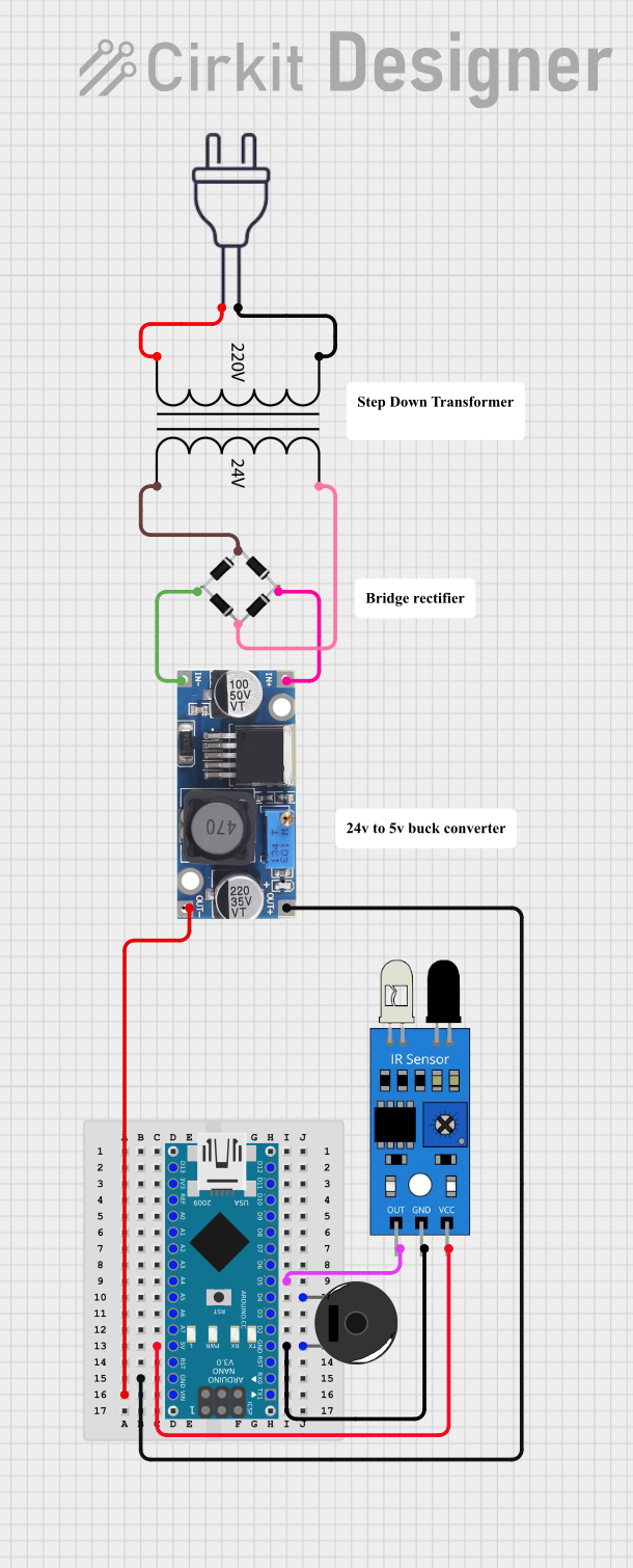
Circuit Documentation
Summary
This document provides a detailed overview of a circuit that includes an Arduino Nano microcontroller, an IR sensor, a Piezo Buzzer, a Power Transformer, a Bridge Rectifier, and a 48V to 5V converter. The circuit is designed to interface an IR sensor with the Arduino Nano, which in turn controls a Piezo Buzzer. The power supply for the circuit is derived from a 220V AC source, which is stepped down and rectified to provide the necessary DC voltages.
Component List
Arduino Nano
- Description: A compact microcontroller board based on the ATmega328P.
- Pins: D1/TX, D0/RX, RESET, GND, D2, D3, D4, D5, D6, D7, D8, D9, D10, D11/MOSI, D12/MISO, VIN, 5V, A7, A6, A5, A4, A3, A2, A1, A0, AREF, 3V3, D13/SCK
IR Sensor
- Description: An infrared sensor used for detecting objects.
- Pins: out, gnd, vcc
Piezo Buzzer
- Description: An electronic device that produces a sound when a voltage is applied.
- Pins: pin 1, pin 2
Power Transformer (220V to 24V)
- Description: A transformer that steps down 220V AC to 24V AC.
- Pins: 2 - Primary, 1 - Primary, 3 - Secondary, 4 - Secondary
48V to 5V Converter
- Description: A DC-DC converter that steps down 48V DC to 5V DC.
- Pins: out+, out--, in+, in--
Bridge Rectifier
- Description: A device that converts AC to DC.
- Pins: Source_in-, source_out-, source_out+, source_in+
Power 220V
- Description: A 220V AC power source.
- Pins: hot wire, neutral wire
Wiring Details
Arduino Nano
- D5 is connected to out of the IR Sensor.
- 5V is connected to vcc of the IR Sensor.
- GND is connected to pin 2 of the Piezo Buzzer and gnd of the IR Sensor.
- GND is connected to out+ of the 48V to 5V Converter.
- VIN is connected to out-- of the 48V to 5V Converter.
- D4 is connected to pin 1 of the Piezo Buzzer.
IR Sensor
- out is connected to D5 of the Arduino Nano.
- vcc is connected to 5V of the Arduino Nano.
- gnd is connected to GND of the Arduino Nano and pin 2 of the Piezo Buzzer.
Piezo Buzzer
- pin 1 is connected to D4 of the Arduino Nano.
- pin 2 is connected to GND of the Arduino Nano and gnd of the IR Sensor.
Power Transformer (220V to 24V)
- 2 - Primary is connected to hot wire of the Power 220V.
- 1 - Primary is connected to neutral wire of the Power 220V.
- 3 - Secondary is connected to source_in+ of the Bridge Rectifier.
- 4 - Secondary is connected to Source_in- of the Bridge Rectifier.
48V to 5V Converter
- in+ is connected to source_out+ of the Bridge Rectifier.
- in-- is connected to source_out- of the Bridge Rectifier.
- out+ is connected to GND of the Arduino Nano.
- out-- is connected to VIN of the Arduino Nano.
Bridge Rectifier
- Source_in+ is connected to 3 - Secondary of the Power Transformer.
- Source_in- is connected to 4 - Secondary of the Power Transformer.
- source_out+ is connected to in+ of the 48V to 5V Converter.
- source_out- is connected to in-- of the 48V to 5V Converter.
Power 220V
- hot wire is connected to 2 - Primary of the Power Transformer.
- neutral wire is connected to 1 - Primary of the Power Transformer.
Documented Code
Arduino Nano Code
void setup() {
  // put your setup code here, to run once:

}

void loop() {
  // put your main code here, to run repeatedly:

}
This code is a basic template for the Arduino Nano. The setup function is used to initialize any settings or configurations, and the loop function contains the main code that runs repeatedly.
This concludes the documentation for the circuit.