
Arduino UNO-Based Sensor Monitoring and Actuator Control System with Solar Charging
View and Edit Project In Cirkit Designer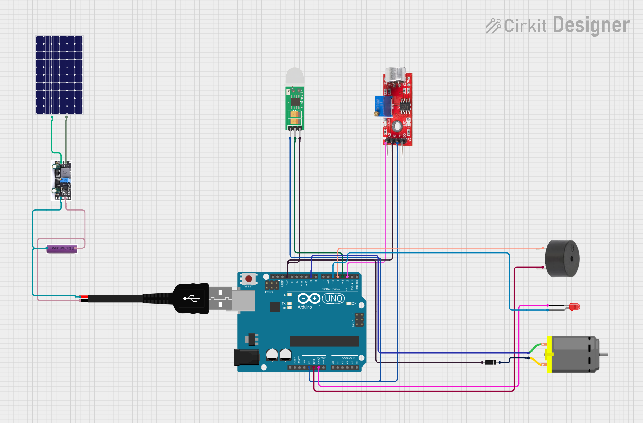
Circuit Documentation
Summary of the Circuit
This circuit is designed to interface various components with an Arduino UNO microcontroller. The components include a sound sensor, a PIR (Passive Infrared) motion sensor, a red LED, a buzzer, a DC motor, a diode, a USB male 2-pin connection, a solar panel, a charge controller, and a 3.7V battery. The circuit is powered by the 3.7V battery, which is charged by the solar panel through the charge controller. The Arduino UNO controls the LED, buzzer, and DC motor based on inputs from the sound sensor and PIR motion sensor.
Component List
- Arduino UNO: A microcontroller board based on the ATmega328P. It has digital input/output pins, analog inputs, a USB connection for programming, and power management features.
- LED (Red, Two Pin): A simple light-emitting diode that emits red light when powered.
- Buzzer: An electronic component that emits sound when powered.
- DC Motor: An electric motor that runs on direct current (DC) electricity.
- Sound Sensor: A sensor that detects sound levels in the environment, typically providing both analog and digital outputs.
- PIR HC-SR505: A mini PIR motion sensor that detects movement within its detection range.
- Diode: A semiconductor device that allows current to flow in one direction only, often used for protecting circuits from reverse voltage.
- USB Male 2 Pin Connection: A connector with two pins for power connections, typically used for USB power supply.
- Solar Panel: A panel that converts sunlight into electrical energy, used for charging the battery.
- Charge Controller: A device that regulates the voltage and current coming from the solar panels going to the battery.
- 3.7V Battery: A rechargeable battery that provides power to the circuit.
Wiring Details
Arduino UNO
- 5V connected to:
- Sound Sensor VCC
- PIR HC-SR505 +
- GND connected to:
- Buzzer GND
- LED cathode
- Sound Sensor GND
- Diode anode
- PIR HC-SR505 -
- D9 connected to DC Motor pin 1
- D5 connected to LED anode
- D4 connected to Buzzer PIN
- D3 connected to PIR HC-SR505 out
- D2 connected to Sound Sensor Analog
LED (Red, Two Pin)
- Cathode connected to Arduino UNO GND
- Anode connected to Arduino UNO D5
Buzzer
- PIN connected to Arduino UNO D4
- GND connected to Arduino UNO GND
DC Motor
- Pin 1 connected to Arduino UNO D9
- Pin 2 connected to Diode cathode
Sound Sensor
- VCC connected to Arduino UNO 5V
- GND connected to Arduino UNO GND
- Analog connected to Arduino UNO D2
PIR HC-SR505
- + connected to Arduino UNO 5V
- Out connected to Arduino UNO D3
- - connected to Arduino UNO GND
Diode
- Anode connected to Arduino UNO GND
- Cathode connected to DC Motor pin 2
USB Male 2 Pin Connection
- Negative - connected to 3.7V Battery -
- Positive + connected to 3.7V Battery +
Solar Panel
- + connected to Charge Controller BAT
- - connected to Charge Controller GND
Charge Controller
- GND connected to:
- 3.7V Battery -
- USB Male 2 Pin Connection Negative -
- BAT connected to Solar Panel +
- Vin connected to:
- 3.7V Battery +
- USB Male 2 Pin Connection Positive +
3.7V Battery
- + connected to:
- USB Male 2 Pin Connection Positive +
- Charge Controller Vin
- - connected to:
- USB Male 2 Pin Connection Negative -
- Charge Controller GND
Documented Code
Arduino UNO Code (sketch.ino)
void setup() {
  // put your setup code here, to run once:

}

void loop() {
  // put your main code here, to run repeatedly:

}
Note: The provided code is a template and does not contain any functional code. It needs to be populated with the logic to control the components based on the inputs from the sensors.