
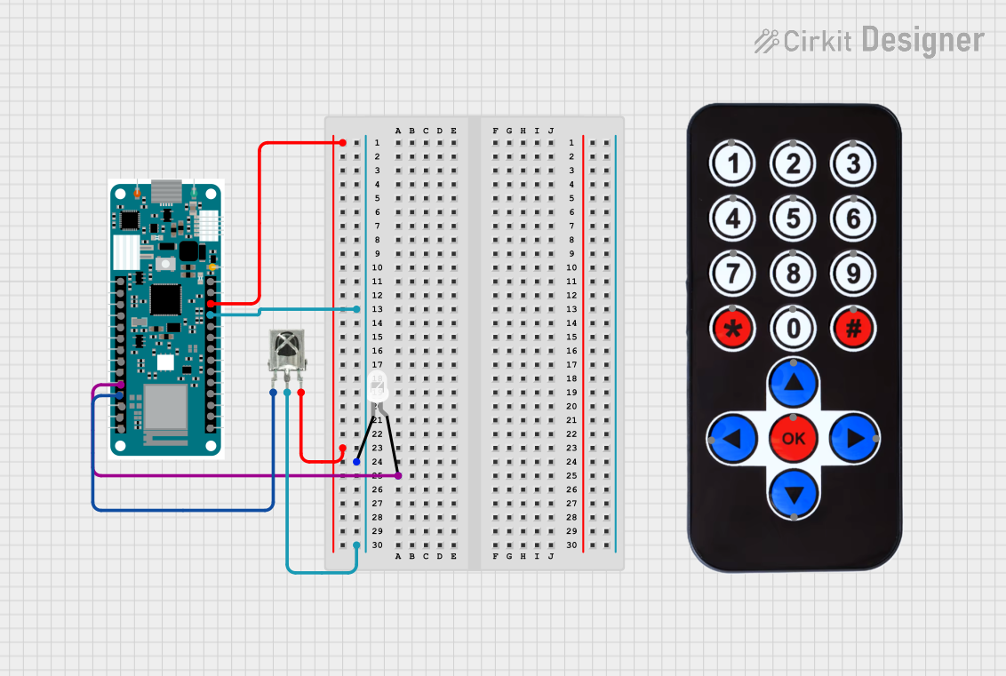
Circuit Documentation
Summary
This circuit consists of an Arduino MKR WiFi 1010 microcontroller, a white LED, an HX1838 Infrared (IR) Wireless Remote Control, and a VS1838B IR Receiver. The circuit is designed to control the LED using the IR remote. When a specific button on the remote is pressed, the LED will turn on or off.
Component List
Arduino MKR WiFi 1010
- Description: A microcontroller board based on the SAMD21 Cortex-M0+ 32-bit ARM processor with built-in WiFi capabilities.
- Pins: A0, A1, A2, A3, A4, A5, A6, D0, D1, D2, D3, D4, D5, D6, D7, MOSI, SCK, MISO, SDA, SCL, RX, TX, RESET, GND, VCC, VIN, 5V
LED: Two Pin (white)
- Description: A white light-emitting diode with two pins: anode and cathode.
- Pins: cathode, anode
HX1838 Infrared IR Wireless Remote Control
- Description: An IR remote control with multiple buttons, each emitting a unique IR signal.
- Pins: FFA25D (1), FF629D (2), FFE21D (3), FF22DD (4), FF02FD (5), FFC23D (6), FFE01F (7), FFA857 (8), FF906F (9), FF9867 (0), FFB04F (#), FF6897 (*), FF18E7 (↑), FF5AA5 (→), FF10EF (←), FF4AB5 (↓), FF38C7 (OK)
VS1838B IR Receiver
- Description: An IR receiver module that can receive IR signals from a remote control.
- Pins: OUT, GND, VCC
Wiring Details
Arduino MKR WiFi 1010
- D2: Connected to the anode of the LED.
- D3: Connected to the OUT pin of the VS1838B IR Receiver.
- VCC: Connected to the VCC pin of the VS1838B IR Receiver.
- GND: Connected to the cathode of the LED and the GND pin of the VS1838B IR Receiver.
LED: Two Pin (white)
- Anode: Connected to D2 of the Arduino MKR WiFi 1010.
- Cathode: Connected to GND of the Arduino MKR WiFi 1010.
HX1838 Infrared IR Wireless Remote Control
- No direct connections: This component communicates with the circuit via IR signals received by the VS1838B IR Receiver.
VS1838B IR Receiver
- OUT: Connected to D3 of the Arduino MKR WiFi 1010.
- GND: Connected to GND of the Arduino MKR WiFi 1010.
- VCC: Connected to VCC of the Arduino MKR WiFi 1010.
Code Documentation
Arduino Code
#include <IRremote.h>

const int RECV_PIN = 3; // Pin connected to the OUT pin of VS1838B
const int LED_PIN = 2;  // Pin connected to the anode of the LED

IRrecv irrecv(RECV_PIN);
decode_results results;

void setup() {
  pinMode(LED_PIN, OUTPUT);
  irrecv.enableIRIn(); // Start the receiver
}

void loop() {
  if (irrecv.decode(&results)) {
    // Example: Turn on the LED when the "1" button is pressed
    if (results.value == 0xFFA25D) { // Replace with the actual code for your remote
      digitalWrite(LED_PIN, HIGH);
    } else {
      digitalWrite(LED_PIN, LOW);
    }
    irrecv.resume(); // Receive the next value
  }
}
This code initializes the IR receiver and sets up the LED pin as an output. In the main loop, it checks if an IR signal has been received. If the signal matches the code for the "1" button on the remote, the LED is turned on. Otherwise, the LED is turned off. The irrecv.resume() function is called to prepare the receiver for the next signal.