
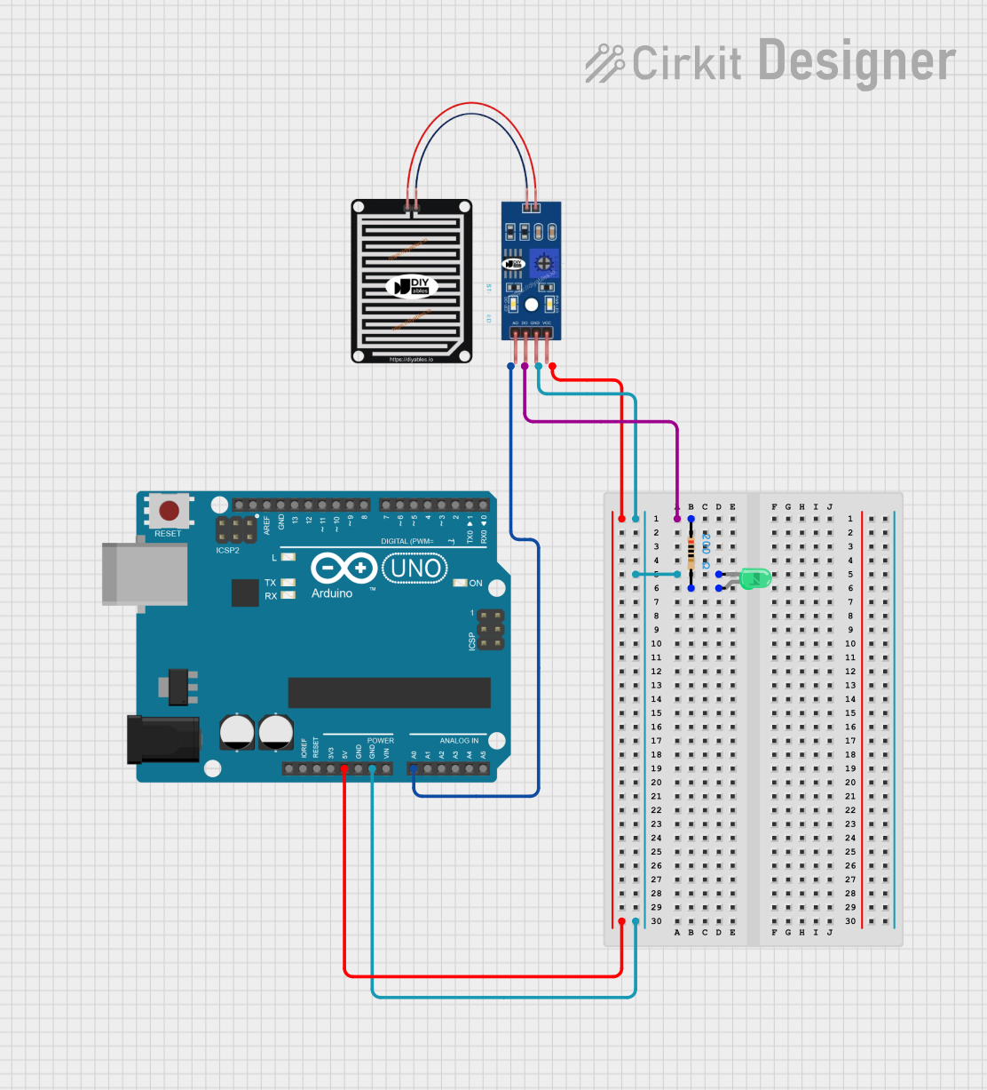
Circuit Documentation
Summary
This document provides a detailed overview of a circuit that includes an Arduino UNO, a rain sensor, a resistor, and a green LED. The circuit is designed to detect rain and potentially indicate the presence of rain using the LED. The Arduino UNO serves as the central microcontroller, interfacing with the rain sensor and controlling the LED.
Component List
Arduino UNO
- Description: A microcontroller board based on the ATmega328P.
- Pins: UNUSED, IOREF, Reset, 3.3V, 5V, GND, Vin, A0, A1, A2, A3, A4, A5, SCL, SDA, AREF, D13, D12, D11, D10, D9, D8, D7, D6, D5, D4, D3, D2, D1, D0
Rain Sensor
- Description: A sensor module used to detect rain.
- Pins: AO, DO, GRD, VCC
Resistor
- Description: A passive electrical component that implements electrical resistance as a circuit element.
- Pins: pin1, pin2
- Properties:
- Resistance: 200 Ohms
LED: Two Pin (green)
- Description: A green light-emitting diode.
- Pins: cathode, anode
Wiring Details
Arduino UNO
- 5V is connected to VCC of the Rain Sensor.
- GND is connected to GRD of the Rain Sensor and cathode of the LED.
- A0 is connected to AO of the Rain Sensor.
Rain Sensor
- DO is connected to pin1 of the Resistor.
- GRD is connected to GND of the Arduino UNO and cathode of the LED.
- VCC is connected to 5V of the Arduino UNO.
- AO is connected to A0 of the Arduino UNO.
Resistor
- pin1 is connected to DO of the Rain Sensor.
- pin2 is connected to anode of the LED.
LED: Two Pin (green)
- cathode is connected to GRD of the Rain Sensor and GND of the Arduino UNO.
- anode is connected to pin2 of the Resistor.
Code Documentation
Arduino UNO Code
sketch.ino
void setup() {
  // put your setup code here, to run once:

}

void loop() {
  // put your main code here, to run repeatedly:

}
documentation.txt
This document provides a comprehensive overview of the circuit, including the components used, their wiring details, and the code running on the Arduino UNO. This should serve as a useful reference for understanding and replicating the circuit.