
Raspberry Pi 5 Battery-Powered Robotic System with Motor Control and IoT Connectivity
View and Edit Project In Cirkit Designer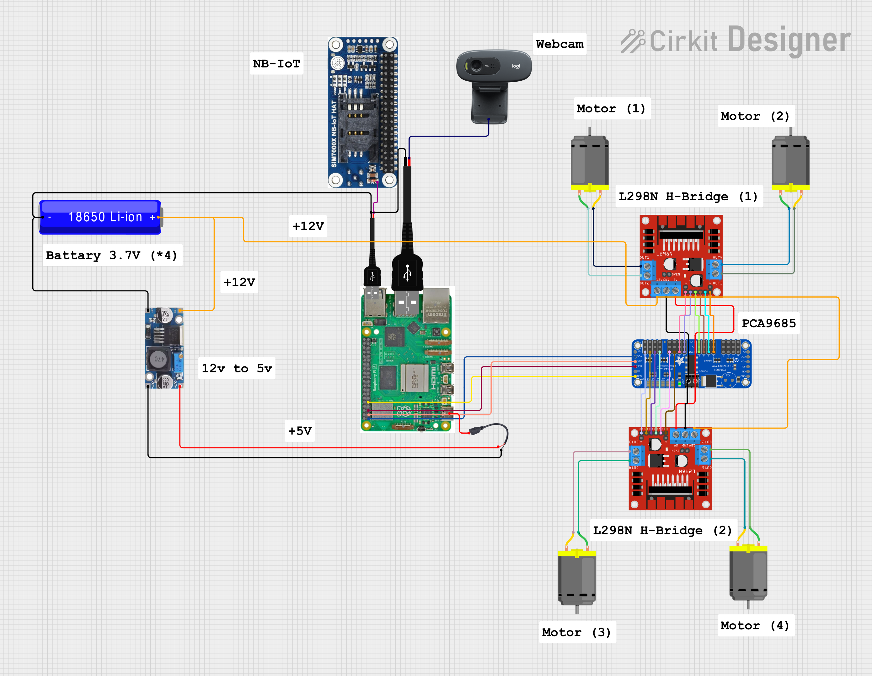
Circuit Documentation
Summary
This document provides a detailed overview of a circuit that integrates a Raspberry Pi 5, various motor drivers, DC motors, a webcam, a SIM7000X NB-IoT HAT, and other components. The circuit is designed to control multiple DC motors and interface with external devices such as a webcam and a SIM7000X module. Power management is handled using a 18650 Li-ion battery and a step-down buck converter.
Component List
Raspberry Pi 5
- Pins: Type-C, Micro HDMI 1, Micro HDMI 2, Camera 1, Camera 2, PoE, Fan, PCIe, USB 3.0, USB 2.0, Ethernet, 5V, GND, 3.3v, GPIO 14, GPIO 15, GPIO 18, GPIO 23, GPIO 24, GPIO 25, GPIO 8, GPIO 7, GPIO 1, GPIO 12, GPIO 16, GPIO 20, GPIO 21, GPIO 2, GPIO 3, GPIO 4, GPIO 17, GPIO 27, GPIO 22, GPIO 10, GPIO 9, GPIO 11, GPIO 0, GPIO 5, GPIO 6, GPIO 13, GPIO 19, GPIO 26
- Description: A versatile single-board computer used for various control and processing tasks.
USB Male 2 Pin Connection
- Pins: Negative -, Positive +
- Description: Used to connect USB devices to the circuit.
Webcam C270
- Pins: None
- Description: A USB webcam used for capturing video.
SIM7000X NB-IoT HAT
- Pins: 1, 2
- Description: A module for cellular communication.
L298N DC Motor Driver
- Pins: OUT1, OUT2, 12V, GND, 5V, OUT3, OUT4, 5V-ENA-JMP-I, 5V-ENA-JMP-O, +5V-J1, +5V-J2, ENA, IN1, IN2, IN3, IN4, ENB
- Description: A dual H-bridge motor driver used to control DC motors.
DC Motor
- Pins: pin 1, pin 2
- Description: A motor used for various mechanical movements.
Adafruit PCA9685 PWM Servo Breakout
- Pins: 5.0V, GND, PWRIN, PWM7, PWM6, PWM5, PWM4, PWM3, PWM2, PWM1, PWM0, VCC, SDA, SCL, OE, PWM15, PWM14, PWM13, PWM12, PWM11, PWM10, PWM9, PWM8
- Description: A PWM driver used to control servos and other PWM devices.
18650 Li-ion Battery
- Pins: -, +
- Description: A rechargeable battery used to power the circuit.
Step Down Buck Converter
- Pins: IN +, IN - GND, OUT +, OUT - GND
- Description: A power converter used to step down voltage.
Micro USB to Cable (2 Pin)
- Pins: Micro USB, +, -
- Description: Used to connect the Raspberry Pi to a power source.
Wiring Details
Raspberry Pi 5
- Type-C connected to Micro USB of Micro USB to Cable (2 Pin).
- 3.3v connected to VCC of Adafruit PCA9685 PWM Servo Breakout.
- GPIO 2 connected to SDA of Adafruit PCA9685 PWM Servo Breakout.
- GPIO 3 connected to SCL of Adafruit PCA9685 PWM Servo Breakout.
- GND connected to GND of Adafruit PCA9685 PWM Servo Breakout.
USB Male 2 Pin Connection
- Negative - connected to - of 18650 Li-ion Battery.
- Negative - connected to IN - GND of Step Down Buck Converter.
- Positive + connected to SIM7000X NB-IoT HAT.
- Positive + connected to Webcam C270.
Webcam C270
- Positive + connected to USB Male 2 Pin Connection.
SIM7000X NB-IoT HAT
- Positive + connected to USB Male 2 Pin Connection.
L298N DC Motor Driver
- OUT1 connected to pin 2 of DC Motor.
- OUT2 connected to pin 1 of DC Motor.
- 12V connected to + of 18650 Li-ion Battery.
- GND connected to GND of Adafruit PCA9685 PWM Servo Breakout.
- 5V connected to PWRIN of Adafruit PCA9685 PWM Servo Breakout.
- OUT3 connected to pin 2 of DC Motor.
- OUT4 connected to pin 1 of DC Motor.
- ENA connected to PWM9 of Adafruit PCA9685 PWM Servo Breakout.
- IN1 connected to PWM8 of Adafruit PCA9685 PWM Servo Breakout.
- IN2 connected to PWM7 of Adafruit PCA9685 PWM Servo Breakout.
- IN3 connected to PWM6 of Adafruit PCA9685 PWM Servo Breakout.
- IN4 connected to PWM5 of Adafruit PCA9685 PWM Servo Breakout.
- ENB connected to PWM4 of Adafruit PCA9685 PWM Servo Breakout.
DC Motor
- pin 1 connected to OUT2 of L298N DC Motor Driver.
- pin 2 connected to OUT1 of L298N DC Motor Driver.
- pin 1 connected to OUT4 of L298N DC Motor Driver.
- pin 2 connected to OUT3 of L298N DC Motor Driver.
Adafruit PCA9685 PWM Servo Breakout
- VCC connected to 3.3v of Raspberry Pi 5.
- SDA connected to GPIO 2 of Raspberry Pi 5.
- SCL connected to GPIO 3 of Raspberry Pi 5.
- GND connected to GND of Raspberry Pi 5.
- PWRIN connected to 5V of L298N DC Motor Driver.
- PWM9 connected to ENA of L298N DC Motor Driver.
- PWM8 connected to IN1 of L298N DC Motor Driver.
- PWM7 connected to IN2 of L298N DC Motor Driver.
- PWM6 connected to IN3 of L298N DC Motor Driver.
- PWM5 connected to IN4 of L298N DC Motor Driver.
- PWM4 connected to ENB of L298N DC Motor Driver.
18650 Li-ion Battery
- - connected to Negative - of USB Male 2 Pin Connection.
- - connected to IN - GND of Step Down Buck Converter.
- + connected to 12V of L298N DC Motor Driver.
- + connected to IN + of Step Down Buck Converter.
Step Down Buck Converter
- IN + connected to + of 18650 Li-ion Battery.
- IN - GND connected to - of 18650 Li-ion Battery.
- OUT + connected to + of Micro USB to Cable (2 Pin).
- OUT - GND connected to - of Micro USB to Cable (2 Pin).
Micro USB to Cable (2 Pin)
- Micro USB connected to Type-C of Raspberry Pi 5.
- + connected to OUT + of Step Down Buck Converter.
- - connected to OUT - GND of Step Down Buck Converter.
Code
No code is provided for this circuit.
This document provides a comprehensive overview of the circuit, including a detailed list of components and their interconnections. This should serve as a useful reference for understanding and troubleshooting the circuit.