ESP8266 NodeMCU Controlled Automated Plant Watering System with Soil Moisture Sensing
Circuit Documentation
Summary
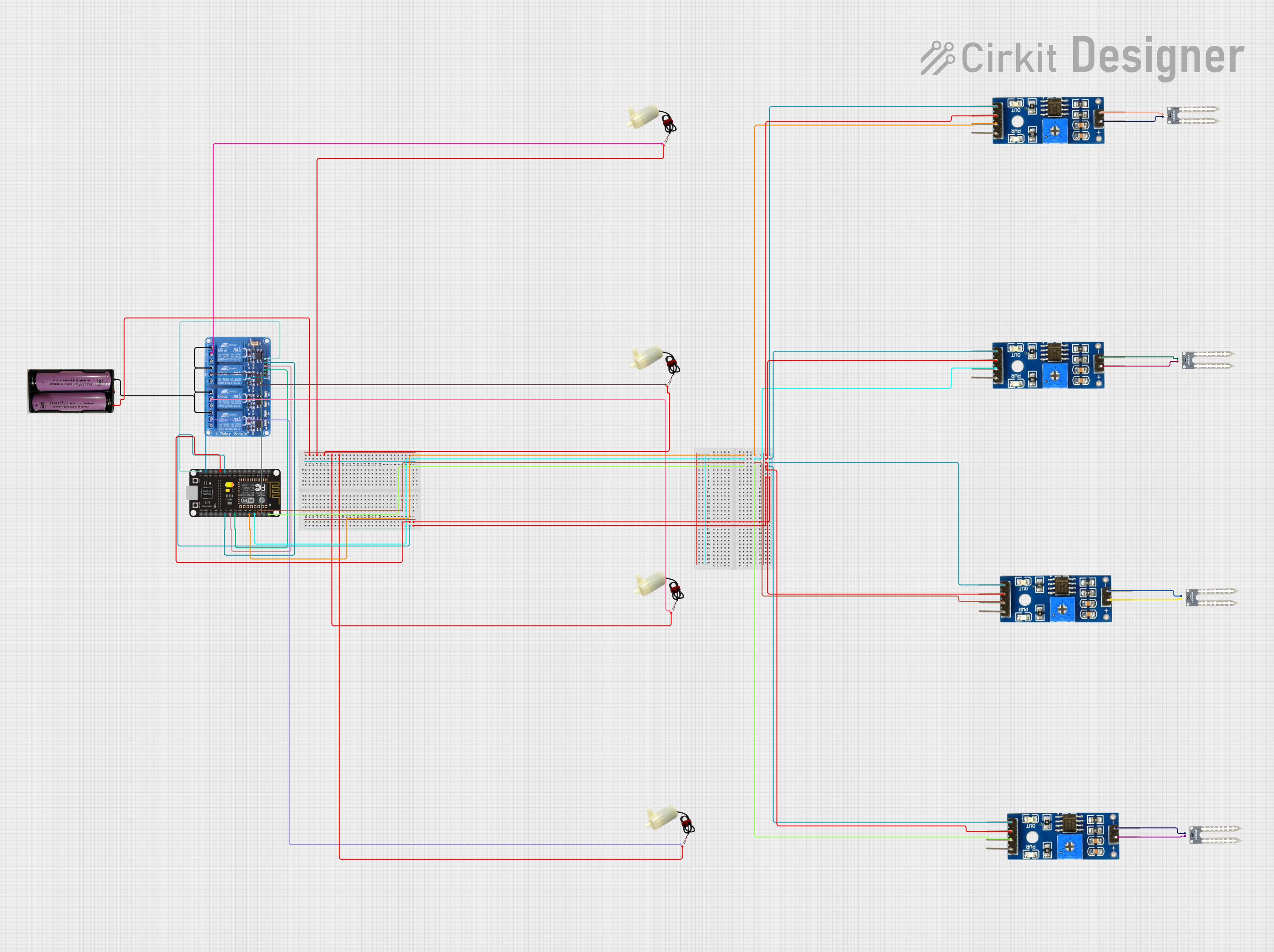
The circuit in question appears to be designed for a soil moisture and water level monitoring system, which can control water pumps based on sensor readings. It includes an ESP8266 NodeMCU microcontroller for processing and control, multiple soil moisture modules and water sensors for monitoring environmental conditions, a relay module to control power to the water pumps, and a power supply to energize the system.
Component List
ESP8266 NodeMCU
- Microcontroller with WiFi capability
- Used for reading sensor data, controlling relays, and possibly communicating with a remote server or user interface.
Relay 4 Channel 5V
- A module with 4 relays capable of controlling higher power devices
- Used to switch the water pumps on and off.
7.4V Power Supply
- Provides power to the relay module and indirectly to the water pumps.
5V Mini Water Pump (4 units)
- Small pumps for moving water
- Controlled by the relay module, used to water plants based on soil moisture readings.
Soil Moisture Module (4 units)
- Sensors that measure the moisture level in the soil
- Provide analog or digital signals to the microcontroller to determine when watering is needed.
Water Sensor (4 units)
- Detects the presence of water
- Used to monitor water levels and possibly to prevent overwatering or detect leaks.
Wiring Details
ESP8266 NodeMCU
3V3connected to VCC of all Soil Moisture ModulesGNDconnected to Ground of all Soil Moisture Modules and Relay 4 Channel 5V GNDD0toD4connected to Digital pins of Soil Moisture ModulesD1,D5,D6,D7connected toIN1,IN2,IN3,IN4on Relay 4 Channel 5VVINconnected to Relay 4 Channel 5V VCC
Relay 4 Channel 5V
GNDconnected to ESP8266 NodeMCU GNDIN1toIN4connected to ESP8266 NodeMCUD1,D5,D6,D7VCCconnected to ESP8266 NodeMCUVINCOM1toCOM4connected to positive pins of each 5V Mini Water PumpNO1toNO4connected to 7.4V Power Supply positive
7.4V Power Supply
+connected toNO1,NO2,NO3,NO4on Relay 4 Channel 5V-connected to negative pins of all 5V Mini Water Pumps
5V Mini Water Pump
positive pinconnected toCOM1,COM2,COM3,COM4on Relay 4 Channel 5Vnegative pinconnected to 7.4V Power Supply negative
Soil Moisture Module
VCCconnected to ESP8266 NodeMCU3V3Groundconnected to ESP8266 NodeMCUGNDDigitalconnected to ESP8266 NodeMCUD0toD4positiveandnegativeconnected to corresponding+and-on Water Sensors
Water Sensor
+connected topositiveon corresponding Soil Moisture Module-connected tonegativeon corresponding Soil Moisture Module
Documented Code
No code has been provided for the microcontroller. The expected code should handle reading sensor data from the soil moisture modules and water sensors, processing the data to make decisions, and controlling the relay module to turn the water pumps on or off accordingly. It may also include functionality for communicating with a remote server or user interface to report sensor readings and system status.