
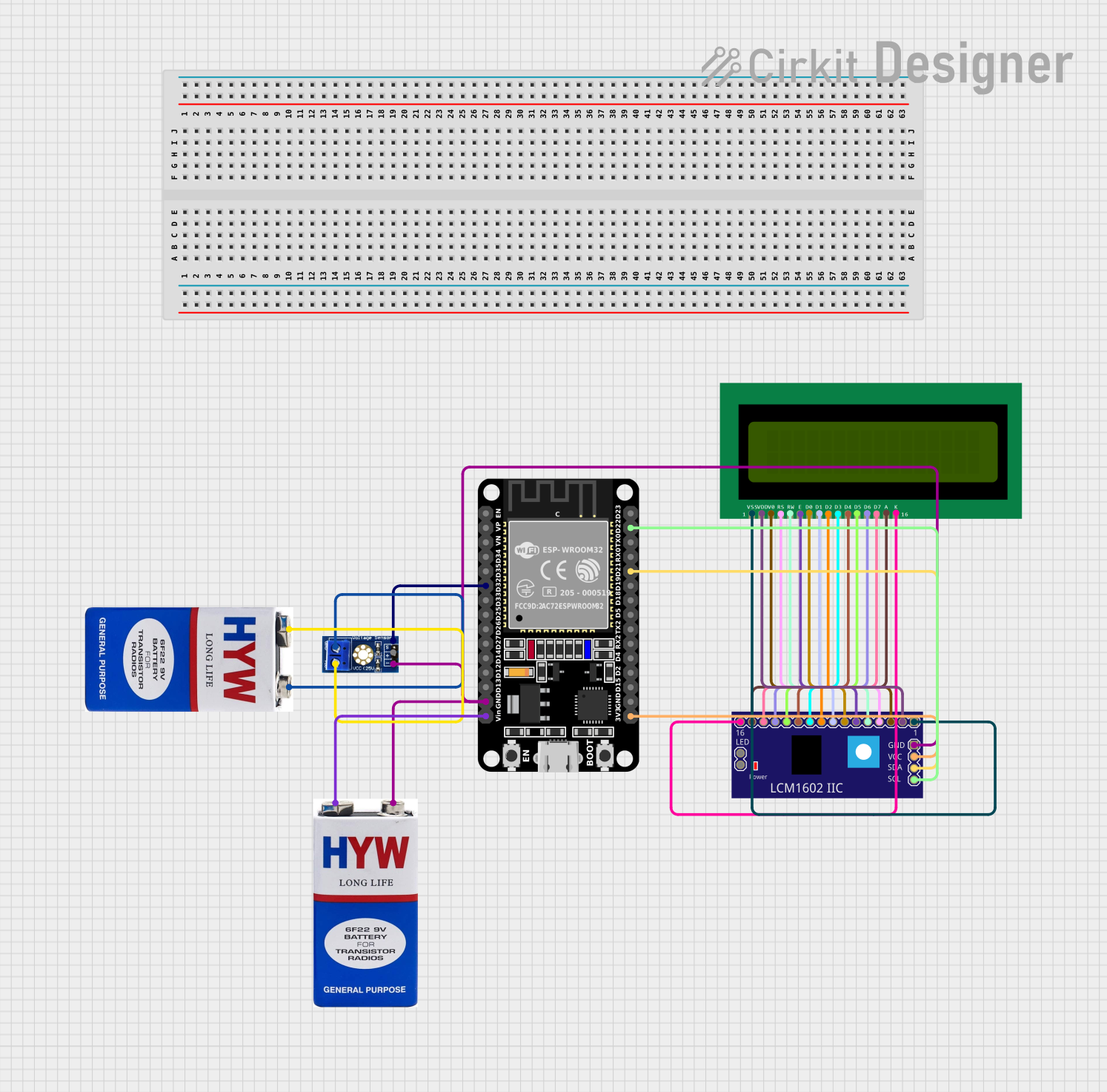
Circuit Documentation
Summary
This circuit integrates an ESP32 microcontroller with a voltage sensor, a 9V battery, and an LCD display module for voltage monitoring purposes. The ESP32 reads the analog voltage level from the voltage sensor and displays the voltage on the LCD. The LCD display is interfaced with the ESP32 via the I2C protocol. The circuit is powered by a 9V battery connected to the ESP32 and the voltage sensor.
Component List
ESP32 (30 pin)
- Description: A 30-pin ESP32 microcontroller module.
- Pins: EN, VP, VN, D34, D35, D32, D33, D25, D26, D27, D14, D12, D13, GND, Vin, D23, D22, TX0, RX0, D21, D19, D18, D5, TX2, RX2, D4, D2, D15, 3V3
Voltage Sensor DC
- Description: A module for sensing DC voltage levels.
- Pins: signal, vcc, gnd, GND, VCC
9V Battery
- Description: A standard 9V battery.
- Pins: +, -
16X2 LCD
- Description: A 16x2 character LCD display.
- Pins: VSS, VDD, V0, RS, RW, E, D1, D0, D2, D3, D4, D6, D5, D7, A, K
LCM1602 IIC
- Description: An I2C interface module for the 16x2 LCD.
- Pins: GND, VCC, SDA, SCL, D6, D7, A, K, VSS, VDD, V0, RS, D2, D3, D4, D5, RW, E, D0, D1, LED_A, LED_B
Wiring Details
ESP32 (30 pin)
- D32 connected to Voltage Sensor DC signal pin
- GND connected to common ground net
- Vin connected to 9V Battery positive terminal
- D22 connected to LCM1602 IIC SCL pin
- D21 connected to LCM1602 IIC SDA pin
- 3V3 connected to LCM1602 IIC VCC pin
Voltage Sensor DC
- signal connected to ESP32 D32 pin
- vcc connected to 9V Battery positive terminal
- gnd connected to common ground net
9V Battery
-
- connected to ESP32 Vin pin and Voltage Sensor DC vcc pin
-
- connected to common ground net
16X2 LCD
- Interfaced through LCM1602 IIC module, all corresponding pins connected to each other (VSS, VDD, V0, RS, RW, E, D0, D1, D2, D3, D4, D5, D6, D7, A, K)
LCM1602 IIC
- GND connected to common ground net
- VCC connected to ESP32 3V3 pin
- SDA connected to ESP32 D21 pin
- SCL connected to ESP32 D22 pin
- All other pins connected to corresponding pins on the 16X2 LCD
Documented Code
#include <Wire.h>
#include <LiquidCrystal_I2C.h>

// Set the LCD I2C address, usually it's 0x27 or 0x3F
LiquidCrystal_I2C lcd(0x27, 16, 2);

// Voltage sensor connected to GPIO 32 (Analog input)
const int voltageSensorPin = 32;

void setup() {
  // Initialize the LCD
  lcd.init();
  // Turn on the backlight
  lcd.backlight();

  // Initialize serial communication for debugging
  Serial.begin(115200);
}

void loop() {
  // Read the analog value from the voltage sensor
  int sensorValue = analogRead(voltageSensorPin);

  // Convert the analog reading (which goes from 0 - 4095) to a voltage (0 - 3.3V):
  float voltage = sensorValue * (3.3 / 4095.0);

  // Print the voltage to the Serial Monitor
  Serial.print("Voltage: ");
  Serial.print(voltage);
  Serial.println(" V");

  // Display the voltage on the LCD
  lcd.setCursor(0, 0); // Set the cursor to column 0, row 0
  lcd.print("Voltage: ");
  lcd.print(voltage);
  lcd.print(" V");

  // Wait a bit before reading again
  delay(1000);
}
This code is designed to run on the ESP32 microcontroller. It initializes the LCD display and reads the voltage from the voltage sensor connected to pin D32. The voltage is then displayed on the LCD and printed to the Serial Monitor for debugging purposes. The analog-to-digital conversion assumes a reference voltage of 3.3V. The code includes a delay of 1 second between readings.