
Arduino UNO and Nano Controlled Temperature Monitoring and Fan Regulation System with OLED Display
View and Edit Project In Cirkit Designer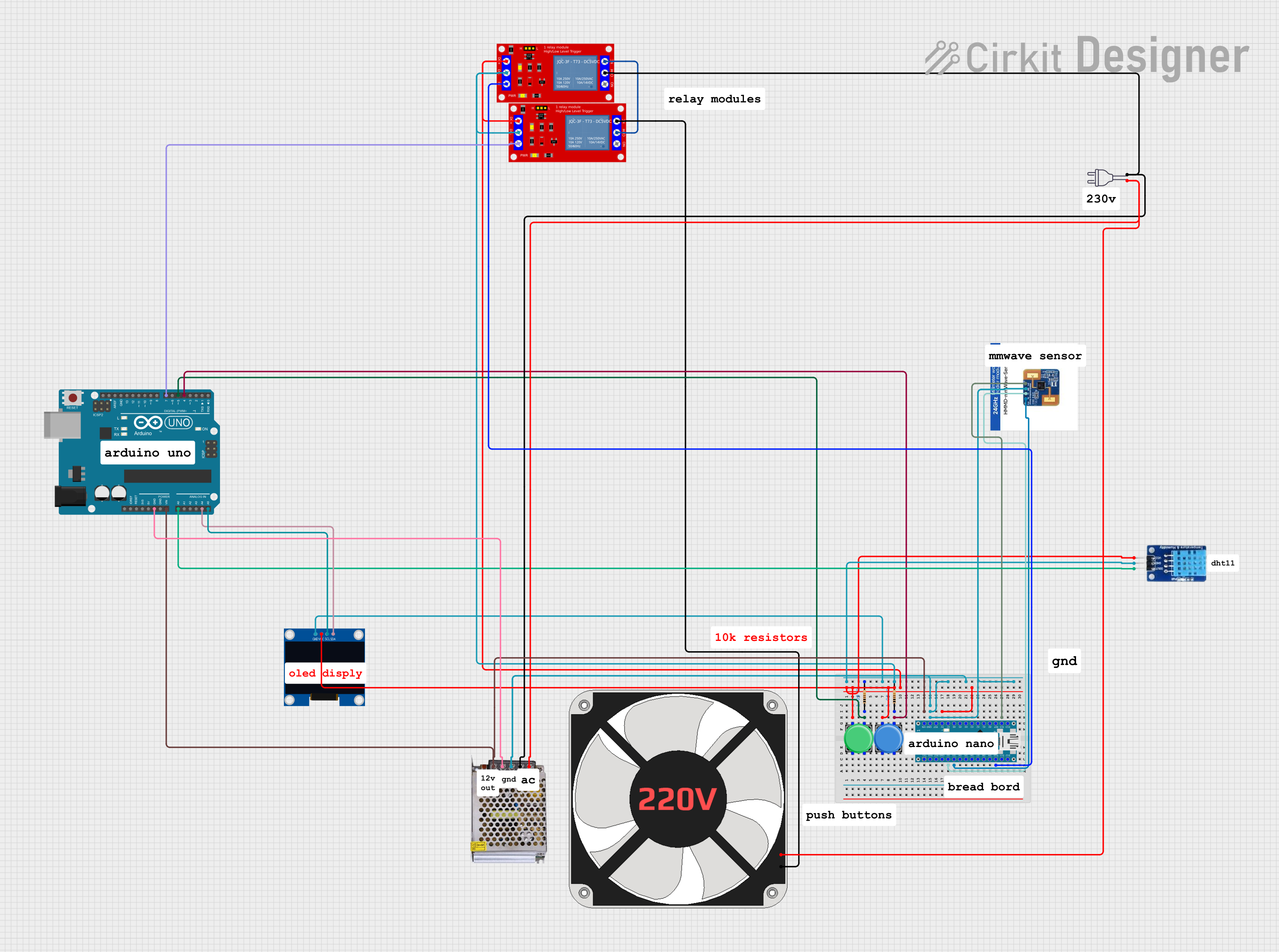
Circuit Documentation
Summary
The circuit in question appears to be a temperature control system utilizing an Arduino UNO and an Arduino Nano as microcontrollers. The system includes a DHT11 temperature and humidity sensor, two 5V relay modules, a 128x64 OLED display for user interface, and pushbuttons for user input. The circuit is powered by a 12V 5A power supply, and it controls a 220V fan through the relay modules. The Arduino UNO is responsible for reading the temperature from the DHT11 sensor, displaying it on the OLED, and controlling the relay based on the temperature set point. The Arduino Nano's role is not fully defined in the provided code.
Component List
- Arduino UNO: A microcontroller board based on the ATmega328P, used for controlling various components of the circuit.
- Arduino Nano: A small, complete, and breadboard-friendly board based on the ATmega328P, used for additional control tasks.
- 1 Channel 5V Relay Module (x2): Modules used to control high power devices such as the 220V fan.
- 128x64 OLED Display (I2C IIC SPI Serial): A display used for showing the temperature and system status.
- DHT11: A basic, ultra low-cost digital temperature and humidity sensor.
- 220V Fan: A fan that operates at 220V, controlled by the relay modules.
- Pushbutton (x2): Buttons used for user input to increase or decrease the temperature set point.
- Resistor (x2): Resistors with a value of 1 Ohm, likely used for debouncing the pushbuttons.
- mmweve: A component with unspecified functionality in this context.
- Power Supply 12V 5A: Provides power to the circuit.
- Comments: There are several "Comment" components listed, which likely contain notes or annotations about the circuit.
Wiring Details
Arduino UNO
- 5V: Connected to pushbuttons and relay modules for power.
- GND: Common ground with the power supply and other components.
- Vin: Receives voltage from the 12V power supply.
- A0: Connected to the DHT11 data pin.
- A4 (SDA): Connected to the OLED display SDA pin for I2C communication.
- A5 (SCL): Connected to the OLED display SCL pin for I2C communication.
- D4: Connected to a pushbutton through a resistor.
- D5: Connected to another pushbutton through a resistor.
- D7: Controls one of the relay modules.
Arduino Nano
- 5V: Powers the DHT11 sensor and the OLED display.
- GND: Common ground with the power supply and other components.
- VIN: Connected to the 12V power supply output.
- D2: Connected to the mmweve TX pin.
- D3: Connected to the mmweve RX pin.
- D10: Controls one of the relay modules.
- 3V3: Powers the mmweve 3v pin.
1 Channel 5V Relay Module
- VCC+: Powered by the 5V output from the Arduino Nano.
- VCC- (GND): Connected to the common ground.
- IN: Controlled by the Arduino Nano (D10) and Arduino UNO (D7).
- COM: Connected to the neutral wire of the power supply.
- N.C.: Normally closed contact, connected between the two relay modules.
- N.O.: Normally open contact, not used in this circuit.
128x64 OLED Display (I2C IIC SPI Serial)
- GND: Connected to the common ground.
- SDA: Connected to the Arduino UNO A4 pin.
- SCL: Connected to the Arduino UNO A5 pin.
- VCC: Powered by the 5V output from the Arduino Nano.
DHT11
- DATA: Connected to the Arduino UNO A0 pin.
- GND: Connected to the common ground.
- VCC: Powered by the 5V output from the Arduino Nano.
Pushbutton
- Pin 1: Connected to the 5V output from the Arduino Nano.
- Pin 3: Connected to the Arduino UNO D4 and D5 pins through resistors.
Resistor
- pin1: Connected to pushbutton pin 3.
- pin2: Connected to the common ground.
mmweve
- 3v: Powered by the 3.3V output from the Arduino Nano.
- gnd: Connected to the common ground.
- tx: Connected to the Arduino Nano D2 pin.
- rx: Connected to the Arduino Nano D3 pin.
Power Supply 12V 5A
- 220V Positive Pole (AC): Connected to the hot wire of the power 220V.
- 220V Negative Pole (AC): Connected to the neutral wire of the power 220V.
- GND: Common ground with the Arduino UNO and other components.
- 12V-24V Output (DC): Provides power to the Arduino Nano VIN pin.
220V Fan
- N: Connected to the normally closed contact of one of the relay modules.
- L: Connected to the hot wire of the power 220V.
Documented Code
Arduino UNO Code (sketch.ino)
#include <U8glib.h>
#include <DHT.h>

U8GLIB_SSD1306_128X64 u8g(U8G_I2C_OPT_NONE);
int posicao = 0;
int temp_max = 30;

#define pino_aumenta 5
#define pino_diminui 4
#define pino_rele 7
#define pino_DHT A0
#define DHTTYPE DHT11

DHT dht(pino_DHT, DHTTYPE);
int temperatura;
int aumenta, diminui;
unsigned long previousMillis = 0;
const long interval = 10000;

void draw() {
  // Display temperature and system status
}

void setup(void) {
  Serial.begin(9600);
  pinMode(pino_rele, OUTPUT);
  pinMode(pino_aumenta, INPUT);
  pinMode(pino_diminui, INPUT);
  dht.begin();
}

void loop(void) {
  // Main program loop
}
This code is responsible for reading the temperature from the DHT11 sensor, displaying it on the OLED screen, and controlling the relay based on the temperature set point. It also handles user input from the pushbuttons to adjust the temperature set point.
Arduino Nano Code (sketch.ino)
void setup() {
  // Setup code here
}

void loop() {
  // Main code here
}
The code for the Arduino Nano is not provided, indicating that its functionality may be minimal or not yet implemented.