
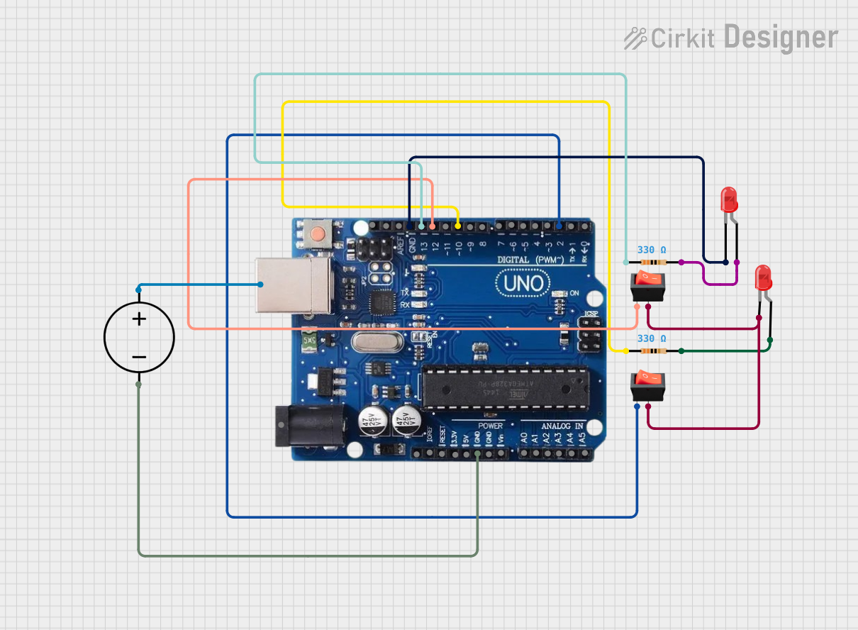
Circuit Documentation
Summary of the Circuit
This circuit is designed to control two LEDs using an Arduino Uno R3 microcontroller. The LEDs can be turned on and off using rocker switches. The Arduino is also programmed to enter a low-power sleep mode when a button is pressed and to wake up from sleep mode when another button is pressed. The circuit includes resistors to limit the current through the LEDs, ensuring they operate safely.
Component List
Resistor
- Description: A resistor is a passive two-terminal electrical component that implements electrical resistance as a circuit element.
- Purpose: In this circuit, resistors are used to limit the current flowing through the LEDs to prevent damage.
- Properties: 330 Ohms
Rocker Switch
- Description: A rocker switch is a type of switch that rocks back and forth when pressed, which means one side of the switch is raised while the other side is depressed.
- Purpose: Rocker switches are used to control the flow of current to the LEDs, effectively turning them on and off.
LED: Two Pin (red)
- Description: A light-emitting diode (LED) is a semiconductor light source that emits light when current flows through it.
- Purpose: The LEDs in this circuit are used as visual indicators.
Arduino Uno R3
- Description: The Arduino Uno R3 is a microcontroller board based on the ATmega328P. It has 14 digital input/output pins, 6 analog inputs, a USB connection, a power jack, an ICSP header, and a reset button.
- Purpose: The Arduino Uno R3 is the central control unit for this circuit, responsible for processing inputs from the rocker switches and controlling the state of the LEDs.
DC Power Source
- Description: A DC power source provides a constant direct current (DC) voltage to an electrical circuit.
- Purpose: The DC power source powers the Arduino Uno R3 and, indirectly, the other components in the circuit.
Wiring Details
Resistor (330 Ohms)
- Connected between the Arduino Uno R3 digital pin 13 and the anode of one LED.
- Connected between the Arduino Uno R3 digital pin 10 and the anode of the other LED.
Rocker Switch
- One switch is connected between the Arduino Uno R3 digital pin 2 and the cathode of one LED.
- The other switch is connected between the Arduino Uno R3 digital pin 12 and the cathode of the other LED.
LED: Two Pin (red)
- The anode of one LED is connected to a 330 Ohm resistor, and its cathode is connected to a rocker switch.
- The anode of the other LED is connected to a 330 Ohm resistor, and its cathode is connected to the other rocker switch.
Arduino Uno R3
- Digital pins 13 and 10 are connected to resistors.
- Digital pins 2 and 12 are connected to rocker switches.
- The GND pin is connected to the cathodes of the LEDs.
- The USB Port is connected to the positive terminal of the DC power source.
- The GND pin is also connected to the ground terminal of the DC power source.
DC Power Source
- The positive terminal is connected to the Arduino Uno R3 USB Port.
- The ground terminal is connected to the Arduino Uno R3 GND pin.
Documented Code
// These are the two libraries that are needed
#include <avr/interrupt.h>
#include <avr/sleep.h>

/* Here we set up our inputs and outputs. LEDs connected to pins 10 and 13 and pushbuttons attached to 2 and 12 */
int ledPin = 13;
int sleepPin = 12;
int interruptPin = 10;
int wakePin = 2;
// sleepStatus is set up to keep track of the button input on pin 12.
int sleepStatus = 0;

void setup()
{
  pinMode(ledPin, OUTPUT);
  pinMode(interruptPin, OUTPUT);
  pinMode(sleepPin, INPUT_PULLUP);
  pinMode(wakePin, INPUT_PULLUP);

  // Enable an interrupt on pin 2 (digital pin 2)
  attachInterrupt(0, wakeUpNow, LOW);
}

void sleepNow()
{
  // Print message to serial monitor to let the user know board has gone to sleep
  Serial.println("going to sleep");
  // Delay to allow user to get the full message on the serial monitor before going to sleep
  delay(15);

  // Enables the sleep mode
  sleep_enable();

  // Enable the interrupt, so that if the button is pressed it doesn't interrupt the running program.
  attachInterrupt(0, wakeUpNow, LOW);

  // Set the sleep mode to power down
  set_sleep_mode(SLEEP_MODE_PWR_DOWN);

  // Put the device to sleep
  sleep_mode();

  // Disable the sleep mode upon waking up
  sleep_disable();

  // Disable the interrupt on pin 2 so the wakeUpNow code will not be executed during normal run time
  detachInterrupt(0);

  // Wait 1 second so the user can notice the LED signaling the interrupt
  delay(1000);
  digitalWrite(interruptPin, LOW);
}

void wakeUpNow()  // This is the code that runs when the interrupt button is pressed and interrupts are enabled
{
  digitalWrite(interruptPin, HIGH);
}

void loop()
{
  // Turn the LED on
  digitalWrite(ledPin, HIGH);
  // Wait for a second
  delay(1000);
  // Turn the LED off
  digitalWrite(ledPin, LOW);
  // Wait for a second
  delay(1000);
  // Read the sleep pin status
  sleepStatus = digitalRead(sleepPin);

  // If button is pressed, run the sleepNow function
  if (sleepStatus == LOW) {
    sleepNow();
  }
}
This code is designed to control the LEDs and manage the sleep mode of the Arduino Uno R3. The setup() function initializes the pins and the interrupt. The loop() function turns the LED on and off and checks the status of the sleep pin. If the sleep pin is pressed, the sleepNow() function is called, which puts the Arduino into a power-down sleep mode. The wakeUpNow() function is the interrupt service routine that wakes up the Arduino from sleep mode.