
Arduino Mega 2560-Based Smart Agriculture System with GSM and Wi-Fi Connectivity
View and Edit Project In Cirkit Designer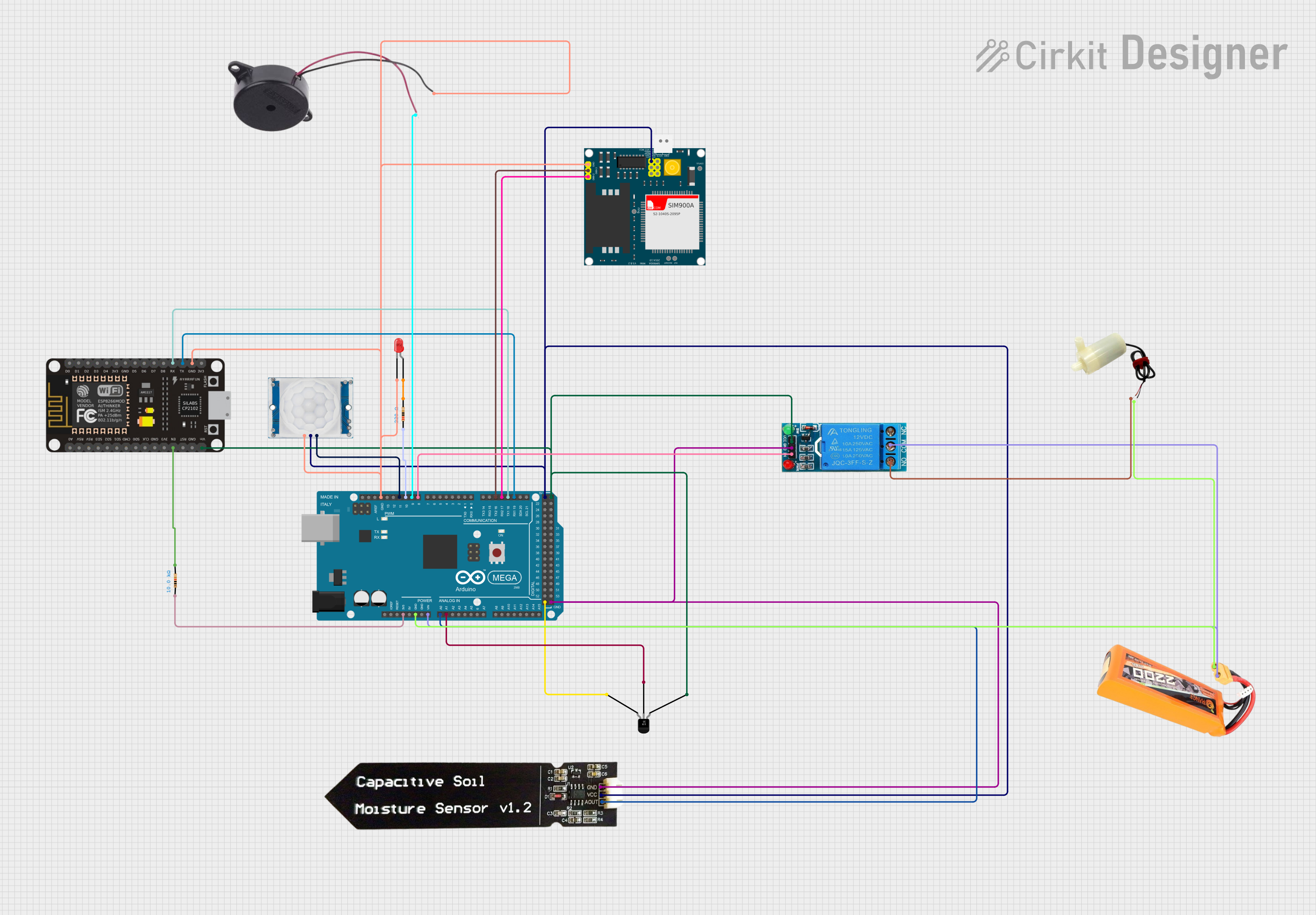
IoT-based Smart Agriculture System Documentation
Summary
This document provides a detailed overview of an IoT-based Smart Agriculture System. The system automates farm management by monitoring environmental conditions such as temperature and soil moisture and controlling irrigation using a water pump. It also sends alerts and updates via a GSM module, enhancing farm efficiency and sustainability with automated and remote monitoring.
Component List
Temperature Sensor (LM35)
- Description: Measures temperature.
- Pins: +Vs, Vout, GND
HC-SR501 PIR Motion Sensor
- Description: Detects motion.
- Pins: Output, Ground, Power Supply
Capacitive Soil Moisture Sensor V1.2
- Description: Measures soil moisture.
- Pins: GND, VCC, AOUT
LED: Two Pin (red)
- Description: Indicates status.
- Pins: Cathode, Anode
Resistor (220 Ohms)
- Description: Limits current.
- Pins: Pin1, Pin2
Resistor (10k Ohms)
- Description: Limits current.
- Pins: Pin1, Pin2
Arduino Mega 2560
- Description: Main microcontroller.
- Pins: IOREF, RESET, 3V3, 5V, GND, VIN, A0-A15, D0-D53, AREF, SDA, SCL
5V Mini Water Pump
- Description: Controls water flow.
- Pins: Positive Pin, Negative Pin
SIM900A
- Description: GSM module for communication.
- Pins: GND, DB9-3 (RXD), DB9-2 (TXD), 5V, 3VR, 5VR, 3VT, 5VT, VCC, Ring, RESTART, RESET, STATUS
12V Single Channel Relay
- Description: Controls high voltage devices.
- Pins: NC, COM, NO, IN, GND, VCC
Buzzer
- Description: Provides audible alerts.
- Pins: Positive, Negative
Lipo Battery 2200mAH 30c
- Description: Power source.
- Pins: VCC, GND
ESP-8266 Controller
- Description: Wi-Fi module for communication.
- Pins: A0, RSV, SD3, SD5, SD1, CMD, D0-D8, RX, TX, Vin, 5V, 3V3, GND, CLK, RST, EN
Wiring Details
Temperature Sensor (LM35)
- +Vs connected to Arduino Mega 2560 5V
- Vout connected to Arduino Mega 2560 A1
- GND connected to Arduino Mega 2560 GND
HC-SR501 PIR Motion Sensor
- Power Supply connected to Arduino Mega 2560 D11 PWM
- Ground connected to Buzzer Negative, ESP-8266 Controller GND, Arduino Mega 2560 GND, LED Cathode, SIM900A GND
- Output connected to Capacitive Soil Moisture Sensor VCC, Arduino Mega 2560 5V, SIM900A VCC
Capacitive Soil Moisture Sensor V1.2
- GND connected to Arduino Mega 2560 GND, 12V Single Channel Relay GND
- VCC connected to HC-SR501 PIR Motion Sensor Output
- AOUT connected to Arduino Mega 2560 A0
LED: Two Pin (red)
- Cathode connected to HC-SR501 PIR Motion Sensor Ground
- Anode connected to Resistor (220 Ohms) Pin2
Resistor (220 Ohms)
- Pin1 connected to Arduino Mega 2560 D10 PWM
- Pin2 connected to LED Anode
Resistor (10k Ohms)
- Pin1 connected to Arduino Mega 2560 3V3
- Pin2 connected to ESP-8266 Controller EN
Arduino Mega 2560
- 3V3 connected to Resistor (10k Ohms) Pin1
- GND connected to Lipo Battery 2200mAH 30c GND, 5V Mini Water Pump Negative Pin, Temperature Sensor (LM35) GND, Capacitive Soil Moisture Sensor GND, 12V Single Channel Relay GND
- VIN connected to Lipo Battery 2200mAH 30c VCC
- A0 connected to Capacitive Soil Moisture Sensor AOUT
- A1 connected to Temperature Sensor (LM35) Vout
- D8 PWM connected to 12V Single Channel Relay IN
- D9 PWM connected to Buzzer Positive
- D10 PWM connected to Resistor (220 Ohms) Pin1
- D11 PWM connected to HC-SR501 PIR Motion Sensor Power Supply
- D16 PWM/TX2 connected to SIM900A DB9-3 (RXD)
- D17 PWM/RX2 connected to SIM900A DB9-2 (TXD)
- D18/TX1 connected to ESP-8266 Controller RX
- D19/RX1 connected to ESP-8266 Controller TX
5V Mini Water Pump
- Positive Pin connected to 12V Single Channel Relay NO
- Negative Pin connected to Arduino Mega 2560 GND
SIM900A
- GND connected to HC-SR501 PIR Motion Sensor Ground
- DB9-3 (RXD) connected to Arduino Mega 2560 D16 PWM/TX2
- DB9-2 (TXD) connected to Arduino Mega 2560 D17 PWM/RX2
- VCC connected to HC-SR501 PIR Motion Sensor Output
12V Single Channel Relay
- COM connected to Lipo Battery 2200mAH 30c VCC
- NO connected to 5V Mini Water Pump Positive Pin
- IN connected to Arduino Mega 2560 D8 PWM
- GND connected to Capacitive Soil Moisture Sensor GND
- VCC connected to Arduino Mega 2560 5V
Buzzer
- Positive connected to Arduino Mega 2560 D9 PWM
- Negative connected to HC-SR501 PIR Motion Sensor Ground
Lipo Battery 2200mAH 30c
- VCC connected to Arduino Mega 2560 VIN, 12V Single Channel Relay COM
- GND connected to Arduino Mega 2560 GND, 5V Mini Water Pump Negative Pin
ESP-8266 Controller
- TX connected to Arduino Mega 2560 D19/RX1
- RX connected to Arduino Mega 2560 D18/TX1
- GND connected to HC-SR501 PIR Motion Sensor Ground
- Vin connected to Temperature Sensor (LM35) +Vs
- EN connected to Resistor (10k Ohms) Pin2
Documented Code
/*
 * IoT-based Smart Agriculture System
 * This Arduino sketch automates farm management by monitoring environmental
 * conditions (temperature, soil moisture) and controlling irrigation using a
 * water pump. The system sends alerts and updates via a GSM module, enhancing
 * farm efficiency and sustainability with automated and remote monitoring.
 */

// Pin definitions
const int soilMoisturePin = A0;
const int tempSensorPin = A1;
const int relayPin = 8;
const int buzzerPin = 9;
const int ledPin = 10;
const int pirSensorPin = 11;
const int gsmTxPin = 16;
const int gsmRxPin = 17;
const int espTxPin = 18;
const int espRxPin = 19;

void setup() {
  // Initialize serial communication
  Serial.begin(9600);
  Serial1.begin(9600); // GSM module
  Serial2.begin(9600); // ESP8266

  // Initialize pins
  pinMode(soilMoisturePin, INPUT);
  pinMode(tempSensorPin, INPUT);
  pinMode(relayPin, OUTPUT);
  pinMode(buzzerPin, OUTPUT);
  pinMode(ledPin, OUTPUT);
  pinMode(pirSensorPin, INPUT);

  // Initial states
  digitalWrite(relayPin, LOW);
  digitalWrite(buzzerPin, LOW);
  digitalWrite(ledPin, LOW);
}

void loop() {
  // Read sensor values
  int soilMoisture = analogRead(soilMoisturePin);
  int tempValue = analogRead(tempSensorPin