
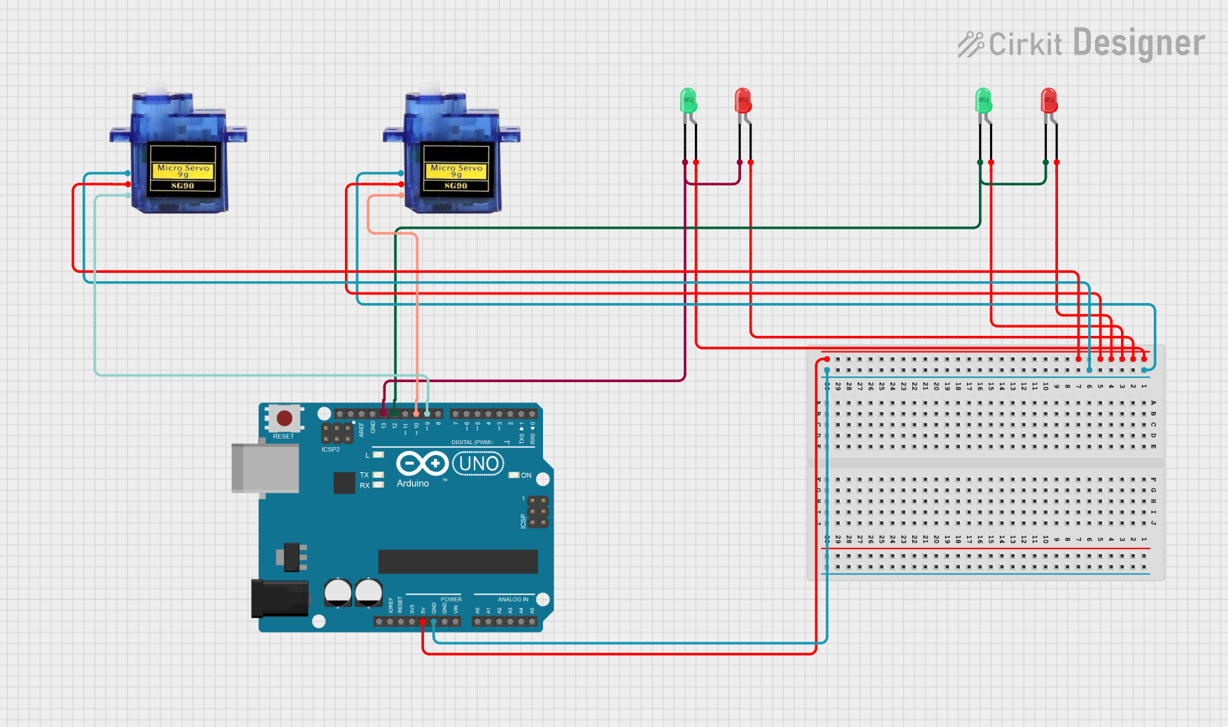
Circuit Documentation
Summary
This circuit involves an Arduino UNO microcontroller controlling two micro servos and four LEDs (two red and two green). The servos are connected to the PWM pins of the Arduino, while the LEDs are connected to digital pins. The circuit is powered by the 5V and GND pins of the Arduino.
Component List
Micro servo 9G
- Pins: GND, +5V, PWM
- Description: A small servo motor used for precise control of angular position.
- Purpose: Used to rotate to specific angles as controlled by the Arduino.
LED: Two Pin (red)
- Pins: Cathode, Anode
- Description: A red light-emitting diode.
- Purpose: Used to indicate status or provide visual feedback.
LED: Two Pin (green)
- Pins: Cathode, Anode
- Description: A green light-emitting diode.
- Purpose: Used to indicate status or provide visual feedback.
Arduino UNO
- Pins: UNUSED, IOREF, Reset, 3.3V, 5V, GND, Vin, A0, A1, A2, A3, A4, A5, SCL, SDA, AREF, D13, D12, D11, D10, D9, D8, D7, D6, D5, D4, D3, D2, D1, D0
- Description: A microcontroller board based on the ATmega328P.
- Purpose: Acts as the main controller for the circuit, executing the embedded code to control the servos and LEDs.
Wiring Details
Micro servo 9G (1)
- GND: Connected to GND of Arduino UNO.
- +5V: Connected to 5V of Arduino UNO.
- PWM: Connected to D10 of Arduino UNO.
Micro servo 9G (2)
- GND: Connected to GND of Arduino UNO.
- +5V: Connected to 5V of Arduino UNO.
- PWM: Connected to D9 of Arduino UNO.
LED: Two Pin (red) (1)
- Cathode: Connected to D13 of Arduino UNO.
- Anode: Connected to 5V of Arduino UNO.
LED: Two Pin (red) (2)
- Cathode: Connected to D12 of Arduino UNO.
- Anode: Connected to 5V of Arduino UNO.
LED: Two Pin (green) (1)
- Cathode: Connected to D13 of Arduino UNO.
- Anode: Connected to 5V of Arduino UNO.
LED: Two Pin (green) (2)
- Cathode: Connected to D12 of Arduino UNO.
- Anode: Connected to 5V of Arduino UNO.
Arduino UNO
- GND: Connected to GND of both Micro servo 9G motors.
- 5V: Connected to +5V of both Micro servo 9G motors and anodes of all LEDs.
- D10: Connected to PWM of Micro servo 9G (1).
- D9: Connected to PWM of Micro servo 9G (2).
- D13: Connected to cathodes of LED: Two Pin (red) (1) and LED: Two Pin (green) (1).
- D12: Connected to cathodes of LED: Two Pin (red) (2) and LED: Two Pin (green) (2).
Code Documentation
#include <Servo.h> //import library

Servo myservo;
int led = 13;

Servo myservo1;
int led1 = 12;

void setup()
{
  pinMode(led, OUTPUT);
  myservo.attach(9, 500, 2500);
  pinMode(led1, OUTPUT);
  myservo1.attach(10, 500, 2500);
}

void loop()
{
  // Rotate Servo 3 by 180 degree
  myservo.write(90);
  myservo1.write(0);
  delay(10);

  digitalWrite(led, HIGH);
  delay(8000);
  digitalWrite(led, LOW);

  myservo.write(0);
  myservo1.write(0);
  delay(1000);

  myservo.write(0);
  myservo1.write(90);
  delay(10);

  digitalWrite(led1, HIGH);
  delay(8000);
  digitalWrite(led1, LOW);

  myservo.write(0);
  myservo1.write(0);
  delay(1000);
}
This code initializes two servo motors and two LEDs. In the setup function, the servos are attached to pins 9 and 10, and the LEDs are set as output on pins 13 and 12. The loop function rotates the servos and toggles the LEDs on and off with delays in between.