
Arduino Mega Controlled Peristaltic Pump and Fan System with Keypad Interface
View and Edit Project In Cirkit Designer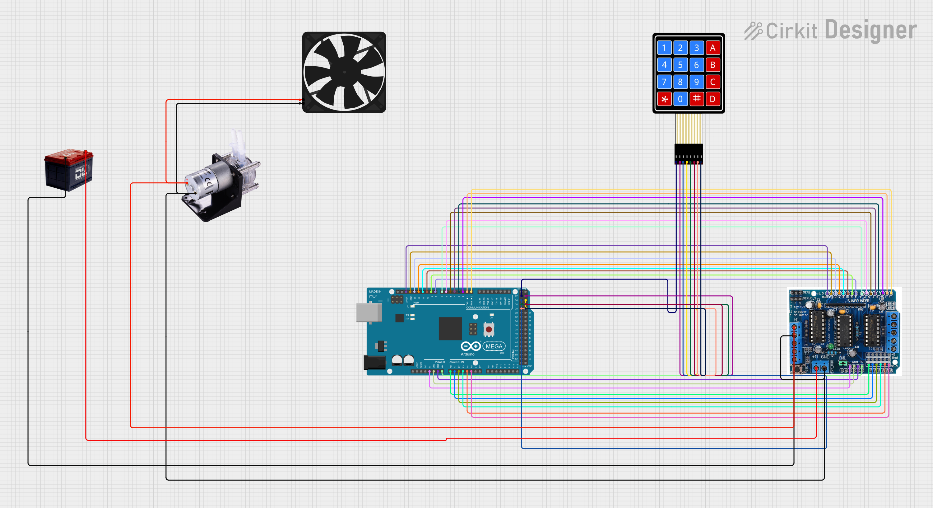
Circuit Documentation
Summary
This circuit is designed to interface an Arduino Mega 2560 with a 4x4 membrane matrix keypad, an L293D motor driver shield, a peristaltic pump, and a fan. The L293D shield is used to control the power delivery to the pump and the fan, while the keypad provides a user interface for input. The Arduino Mega 2560 serves as the central processing unit, running the embedded code to manage the inputs and outputs of the system. The circuit is powered by a 12V battery, which supplies power to the motor driver shield and, through it, to the pump and fan.
Component List
Battery 12v
- Description: A 12-volt battery providing the main power source for the circuit.
- Pins:
-(Negative),+(Positive)
Arduino Mega 2560
- Description: A microcontroller board based on the ATmega2560, with numerous digital and analog I/O pins.
- Pins: IOREF, RESET, 3V3, 5V, GND, VIN, Analog Pins (A0-A15), Digital Pins (D0-D53), PWM Pins (D2-D13), Communication Pins (TX, RX, SCL, SDA), AREF
4X4 Membrane Matrix Keypad
- Description: A keypad with 16 buttons arranged in a 4x4 matrix, used for user input.
- Pins: R1, R2, R3, R4, C1, C2, C3, C4
L293D Motor Driver Shield
- Description: A shield for the Arduino that can control up to 4 DC motors with 8-bit speed selection and 2 servos.
- Pins: 5v, GND, Analog Pins (A0-A5), Motor Power (M+, M1-M4), Digital Pins (0-12), Aref, Servo Power (Servo1, Servo2), Power Pins (+, -, 9v)
Peristaltic Pump
- Description: A type of positive displacement pump used for pumping a variety of fluids.
- Pins:
+(Positive),-(Negative)
Fan
- Description: An electric fan used for cooling or ventilation.
- Pins: GND, 5V
Wiring Details
Battery 12v
+connected to L293D Motor Driver ShieldM+-connected to L293D Motor Driver ShieldGND
Arduino Mega 2560
- Analog Pins (A0-A5) connected to L293D Motor Driver Shield (A0-A5)
- Digital Pins (D0-D13) connected to L293D Motor Driver Shield (0-12)
GNDconnected to L293D Motor Driver Shieldgnd5Vconnected to L293D Motor Driver Shield5vAREFconnected to L293D Motor Driver ShieldArefVINconnected to L293D Motor Driver Shield9v- Digital Pins (D22-D29) connected to 4X4 Membrane Matrix Keypad (R1-R4, C1-C4)
L293D Motor Driver Shield
A0-A5connected to Arduino Mega 2560 (A0-A5)M+connected to Battery 12v+GNDconnected to Battery 12v-M1connected to Peristaltic Pump+and Fan5V- Digital Pins (0-12) connected to Arduino Mega 2560 (D0-D13)
Arefconnected to Arduino Mega 2560AREF5vconnected to Arduino Mega 25605Vgndconnected to Arduino Mega 2560GND9vconnected to Arduino Mega 2560VIN
Peristaltic Pump
+connected to L293D Motor Driver ShieldM1-connected to Battery 12v-
Fan
5Vconnected to L293D Motor Driver ShieldM1GNDconnected to Battery 12v-
4X4 Membrane Matrix Keypad
R1-R4connected to Arduino Mega 2560 (D22, D24, D25, D23)C1-C4connected to Arduino Mega 2560 (D26, D27, D28, D29)
Documented Code
Arduino Mega 2560 - sketch.ino
void setup() {
  // put your setup code here, to run once:

}

void loop() {
  // put your main code here, to run repeatedly:

}
Arduino Mega 2560 - documentation.txt
(No additional documentation provided for the code)
This concludes the documentation for the given circuit. The code provided is a template and does not contain any functional implementation. It is expected that the user will write the necessary setup and loop functions to control the circuit's components based on the wiring and the desired behavior.