Cirkit Designer
Your all-in-one circuit design IDE
Home /
Project Documentation
Arduino-Controlled Robotics Platform with Proximity and Ultrasonic Sensing

Circuit Documentation
Summary
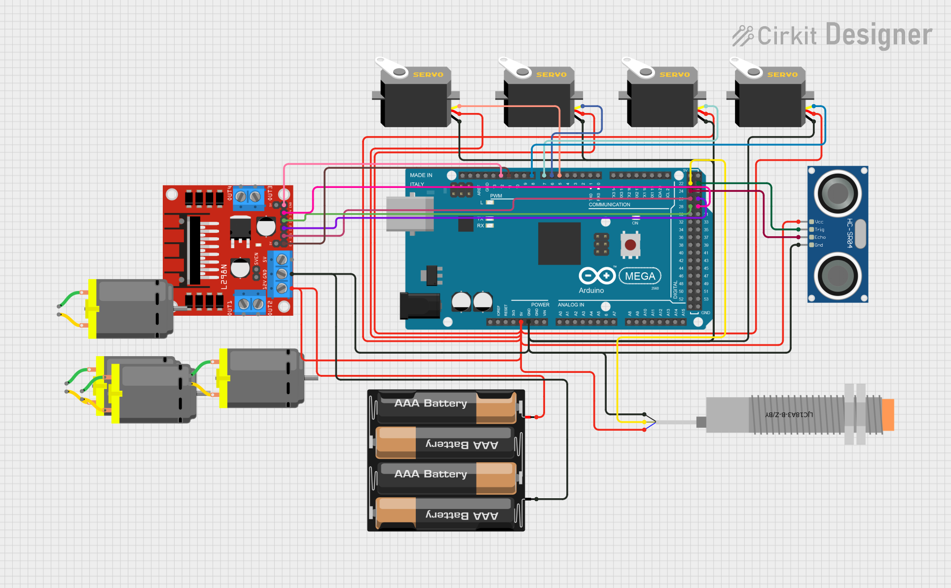
This circuit is designed to interface various components with an Arduino Mega 2560 microcontroller. The components include capacitive proximity sensors, ultrasonic sensors, servo motors, a DC motor driver, and DC motors. The circuit is powered by a 4 x AAA battery mount, and it features both power and signal connections to the Arduino Mega 2560. The microcontroller is programmed to control the servo motors and DC motors, as well as to receive input from the sensors.
Component List
LJC18A3-B-Z/BY Capacitive Proximity Sensor
- Pins: VO (BLU), VI (BRN), SIG (BLK)
- Description: A sensor used to detect the presence of objects without physical contact.
Servo Motor
- Pins: gnd, vcc, pulse
- Description: An actuator that can be precisely controlled in terms of angular position.
L298N DC Motor Driver
- Pins: OUT1, OUT2, 12V, GND, 5V, OUT3, OUT4, 5V-ENA-JMP-I, 5V-ENA-JMP-O, +5V-J1, +5V-J2, ENA, IN1, IN2, IN3, IN4, ENB
- Description: A module used to control the direction and speed of DC motors.
HC-SR04 Ultrasonic Sensor
- Pins: VCC, TRIG, ECHO, GND
- Description: A sensor used to measure distance by emitting ultrasonic waves and detecting their reflection.
4 x AAA Battery Mount
- Pins: -, +
- Description: A battery holder for four AAA batteries, providing power to the circuit.
Arduino Mega 2560
- Pins: Multiple digital and analog I/O pins, power, and ground pins.
- Description: A microcontroller board based on the ATmega2560, with extensive I/O capabilities.
DC Motor
- Pins: pin 1, pin 2
- Description: An electric motor that runs on direct current (DC) electricity.
Wiring Details
LJC18A3-B-Z/BY Capacitive Proximity Sensor
- VO (BLU) connected to 5V power rail
- VI (BRN) connected to Arduino Mega 2560 pin D22
- SIG (BLK) connected to GND
Servo Motors
- vcc connected to 5V power rail
- gnd connected to GND
- pulse connected to Arduino Mega 2560 pins D5 PWM, D6 PWM, D7 PWM, D8 PWM (one servo per pin)
L298N DC Motor Driver
- 12V connected to 5V power rail
- GND connected to GND
- ENA connected to Arduino Mega 2560 pin D11 PWM
- IN1 connected to Arduino Mega 2560 pin D26
- IN2 connected to Arduino Mega 2560 pin D27
- IN3 connected to Arduino Mega 2560 pin D28
- IN4 connected to Arduino Mega 2560 pin D29
- ENB connected to Arduino Mega 2560 pin D12 PWM
HC-SR04 Ultrasonic Sensor
- VCC connected to 5V power rail
- TRIG connected to Arduino Mega 2560 pin D23
- ECHO connected to Arduino Mega 2560 pin D24
- GND connected to GND
4 x AAA Battery Mount
- + connected to 5V power rail
- - connected to GND
DC Motors
- Connected to the L298N DC Motor Driver OUT1, OUT2, OUT3, OUT4 (one motor per pair of outputs)
Documented Code
Arduino Mega 2560 (sketch.ino)
void setup() {
  // put your setup code here, to run once:

}

void loop() {
  // put your main code here, to run repeatedly:

}
Additional Notes
- The provided code is a template and does not contain any functional code for controlling the components.
- The user should implement the setup and loop functions to initialize the components and define the behavior of the circuit.
- The code should include initialization of the pins as inputs or outputs, as well as the logic for reading sensor data and controlling the motors.