Cirkit Designer
Your all-in-one circuit design IDE
Home /
Project Documentation
Arduino UNO Based Temperature Monitoring System with LCD Display
Circuit Documentation
Summary
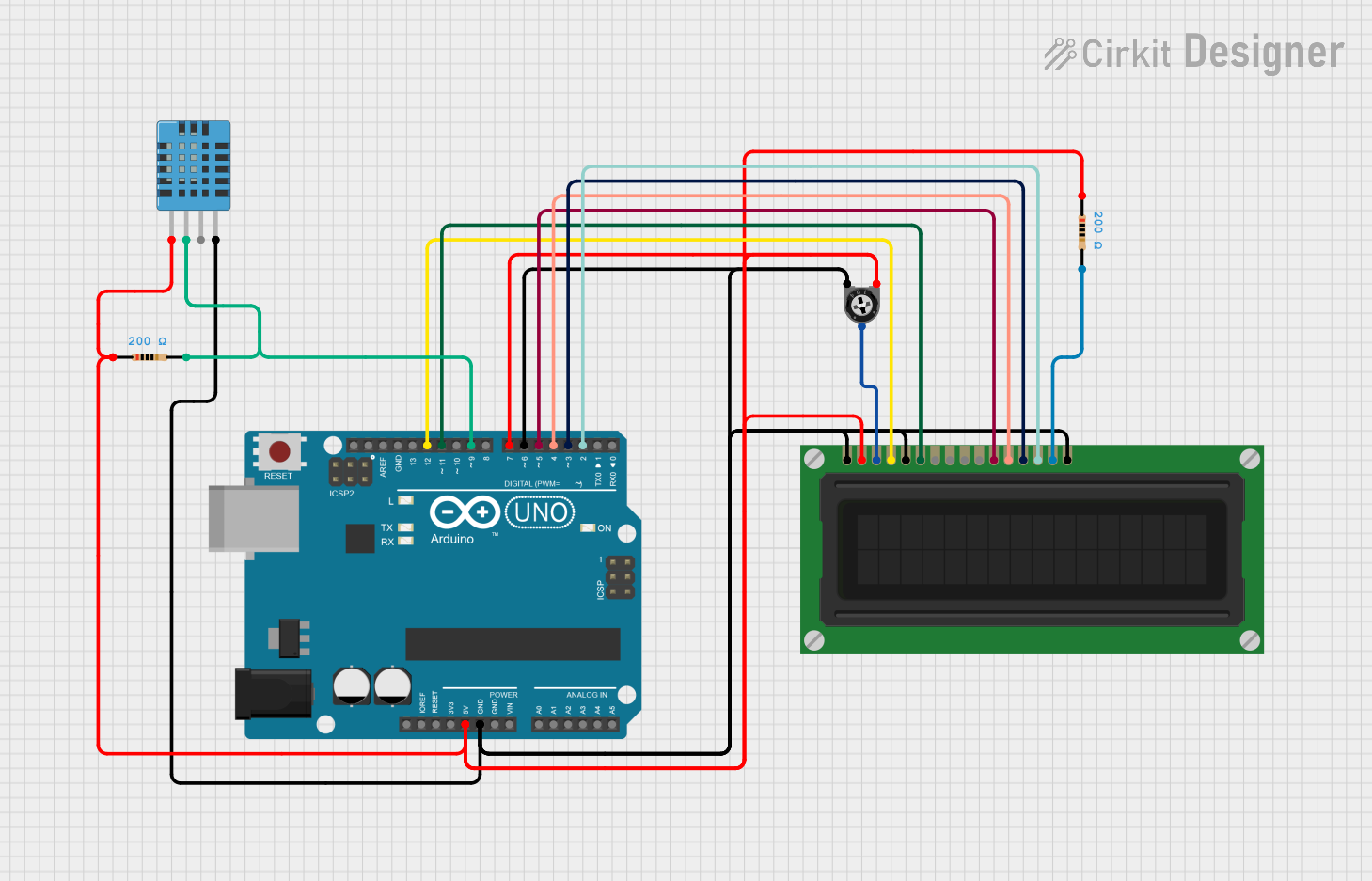
This circuit is designed to interface an Arduino UNO with an LCD display and a DHT11 humidity and temperature sensor. The LCD display is used to show the temperature readings captured by the DHT11 sensor. A trimmer potentiometer is included to adjust the contrast of the LCD, and resistors are used for current limiting and pull-up configurations.
Component List
LCD Display (16 pin)
- Description: A 16-pin liquid crystal display used to show information.
- Purpose: To display temperature readings from the DHT11 sensor.
Trimmer Potentiometer
- Description: A variable resistor with a range of 10k Ohms.
- Purpose: To adjust the contrast of the LCD display.
Resistor (Instance 1)
- Description: A fixed resistor with a resistance of 200 Ohms.
- Purpose: To limit current to the backlight of the LCD.
Resistor (Instance 2)
- Description: A fixed resistor with a resistance of 200 Ohms.
- Purpose: To act as a pull-up resistor for the DHT11 data line.
DHT11 Humidity and Temperature Sensor
- Description: A sensor that measures ambient humidity and temperature.
- Purpose: To provide temperature readings to be displayed on the LCD.
Arduino UNO
- Description: A microcontroller board based on the ATmega328P.
- Purpose: To control the LCD display and read data from the DHT11 sensor.
Wiring Details
LCD Display
- VDD: Connected to 5V power supply from Arduino UNO.
- VSS, K, R_W: Connected to GND.
- RS: Connected to digital pin D12 on Arduino UNO.
- E: Connected to digital pin D11 on Arduino UNO.
- DB4: Connected to digital pin D5 on Arduino UNO.
- DB5: Connected to digital pin D4 on Arduino UNO.
- DB6: Connected to digital pin D3 on Arduino UNO.
- DB7: Connected to digital pin D2 on Arduino UNO.
- VO: Connected to the wiper of the trimmer potentiometer.
- A: Connected to one end of a 200 Ohm resistor, the other end connected to 5V.
Trimmer Potentiometer
- Leg1: Connected to 5V power supply.
- Wiper: Connected to VO pin on LCD for contrast adjustment.
- Leg2: Connected to GND.
Resistor (Instance 1)
- Pin1: Connected to 5V power supply.
- Pin2: Connected to A pin on LCD for backlight current limiting.
Resistor (Instance 2)
- Pin1: Connected to DHT11 DATA pin.
- Pin2: Connected to digital pin D9 on Arduino UNO for pull-up configuration.
DHT11 Sensor
- VDD: Connected to 5V power supply.
- DATA: Connected to digital pin D9 on Arduino UNO through a 200 Ohm pull-up resistor.
- GND: Connected to GND.
Arduino UNO
- 5V: Provides power to LCD VDD, trimmer potentiometer leg1, and DHT11 VDD.
- GND: Connected to LCD VSS, K, R_W, trimmer potentiometer leg2, and DHT11 GND.
- D12: Controls RS pin on LCD.
- D11: Controls E pin on LCD.
- D5: Controls DB4 pin on LCD.
- D4: Controls DB5 pin on LCD.
- D3: Controls DB6 pin on LCD.
- D2: Controls DB7 pin on LCD.
- D9: Reads DATA from DHT11 sensor.
Documented Code
#include <LiquidCrystal.h>
#include <DHT.h>

// Initialize the LCD with the numbers of the interface pins
LiquidCrystal lcd(12, 11, 5, 4, 3, 2);

// Define the DHT sensor pin and type
#define DHTPIN 9
#define DHTTYPE DHT11

// Initialize the DHT sensor
DHT dht(DHTPIN, DHTTYPE);

unsigned long startTime;
float previousTemperature = NAN;

void setup() {
  // Set up the LCD's number of columns and rows
  lcd.begin(16, 2);

  // Print a message to the LCD
  lcd.print("Initializing...");

  // Initialize the start time
  startTime = millis();

  // Initialize the DHT sensor
  dht.begin();

  pinMode(6, OUTPUT);
  pinMode(7, OUTPUT);

  digitalWrite(6, LOW);
  digitalWrite(7, HIGH);
}

void loop() {
  // Calculate the elapsed time in milliseconds
  unsigned long elapsedTime = millis() - startTime;

  // Convert elapsed time to seconds with one decimal place
  float elapsedTimeSec = elapsedTime / 1000.0;

  // Read temperature as Celsius
  float temperature = dht.readTemperature();

  // Check if any reads failed and exit early (to try again).
  if (isnan(temperature)) {
    lcd.setCursor(0, 0);
    lcd.print("Error reading");
    return;
  }

  // Only update the display if the temperature has changed
  if (temperature != previousTemperature) {
    // Clear the first row
    lcd.setCursor(0, 0);
    lcd.print("                "); // Clear the first row by printing spaces

    // Set the cursor to the first row, first column
    lcd.setCursor(0, 0);
    lcd.print("Temp: ");

    // Clear the second row
    lcd.setCursor(0, 1);
    lcd.print("                "); // Clear the second row by printing spaces

    // Set the cursor to the second row, first column
    lcd.setCursor(0, 1);

    // Print the temperature to the LCD
    lcd.print(temperature);
    lcd.print(" C");

    // Update the previous temperature
    previousTemperature = temperature;
  }

  // Add a small delay to avoid flickering
  delay(50);
}
This code initializes the LCD and DHT11 sensor, then enters a loop where it reads the temperature and displays it on the LCD. If the temperature reading fails, it displays an error message. The display is updated only when the temperature changes to minimize flickering.