
Arduino Nano-Based Piezo Sensor Data Logger with SD Card Storage
View and Edit Project In Cirkit Designer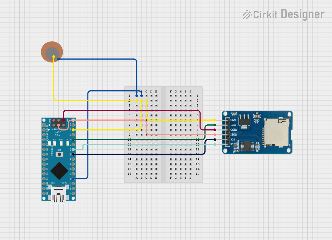
Circuit Documentation
Summary of the Circuit
This circuit is designed to capture voltage data from a piezo sensor and log this data to a file on an SD card. The piezo sensor is interfaced with an Arduino Nano microcontroller, which reads the sensor's voltage and writes the data to the SD card using a Micro SD Card Module. The data logging occurs at a rate of 10 samples per second. The Arduino Nano communicates with the SD card module via the SPI (Serial Peripheral Interface) protocol.
Component List
Piezo Sensor
- Description: A sensor that generates a voltage when it is deformed by pressure or vibration.
- Pins:
+: Positive terminal-: Negative terminal
Arduino Nano
- Description: A small, complete, and breadboard-friendly microcontroller board based on the ATmega328P.
- Pins:
- Digital I/O Pins: D0 - D13
- Analog Input Pins: A0 - A7
- Power Pins: 3V3, 5V, GND, VIN
- SPI Pins: D11/MOSI, D12/MISO, D13/SCK
- Other Pins: RESET, AREF
Micro SD Card Module
- Description: A module that allows microcontrollers to interface with a micro SD card using SPI for data storage.
- Pins:
cs: Chip Selectsck: Serial Clockmosi: Master Out Slave Inmiso: Master In Slave Outvcc: Power supplygnd: Ground
Wiring Details
Piezo Sensor
+(Positive terminal) is connected toGNDon the Arduino Nano.-(Negative terminal) is connected toA0on the Arduino Nano.
Arduino Nano
A0is connected to the negative terminal of the Piezo Sensor.GNDis connected to the positive terminal of the Piezo Sensor andgndon the Micro SD Card Module.5Vis connected tovccon the Micro SD Card Module.A6is connected tocson the Micro SD Card Module.A5is connected tosckon the Micro SD Card Module.D12/MISOis connected tomisoon the Micro SD Card Module.D11/MOSIis connected tomosion the Micro SD Card Module.
Micro SD Card Module
csis connected toA6on the Arduino Nano.sckis connected toA5on the Arduino Nano.mosiis connected toD11/MOSIon the Arduino Nano.misois connected toD12/MISOon the Arduino Nano.vccis connected to5Von the Arduino Nano.gndis connected toGNDon the Arduino Nano.
Documented Code
/*
 * This Arduino sketch reads voltage data from a piezo sensor connected to A0
 * and stores the data in a file on an SD card. The SD card module is connected
 * to the Arduino Nano via SPI interface. The Arduino reads the piezo sensor
 * voltage 10 times per second and logs the data to the SD card.
 */

#include <SPI.h>
#include <SD.h>

const int piezoPin = A0; // Pin connected to the piezo sensor
const int chipSelect = A6; // Pin connected to the SD card module's CS pin

File dataFile;

void setup() {
  Serial.begin(9600);
  pinMode(piezoPin, INPUT);
  if (!SD.begin(chipSelect)) {
    Serial.println("SD card initialization failed!");
    return;
  }
  Serial.println("SD card initialized.");
  dataFile = SD.open("datalog.txt", FILE_WRITE);
  if (!dataFile) {
    Serial.println("Error opening datalog.txt");
  }
}

void loop() {
  int sensorValue = analogRead(piezoPin);
  if (dataFile) {
    dataFile.println(sensorValue);
    dataFile.flush();
  } else {
    Serial.println("Error writing to datalog.txt");
  }
  delay(100); // Delay for 100 milliseconds (10 readings per second)
}
The code is written for an Arduino Nano and is responsible for initializing the SD card, reading the voltage from the piezo sensor, and logging the data to a file named "datalog.txt" on the SD card. The setup() function initializes the serial communication, sets up the piezo sensor pin as an input, and prepares the SD card for data logging. The loop() function reads the sensor value and writes it to the SD card every 100 milliseconds.