
Circuit Documentation
Summary of the Circuit
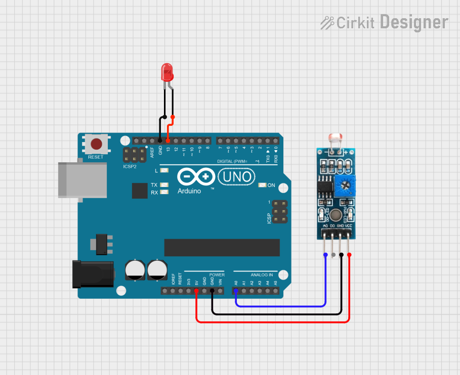
This circuit consists of an Arduino UNO microcontroller, a Module LDR (Light Dependent Resistor), and a red two-pin LED. The Arduino UNO is used as the central processing unit to read the analog value from the LDR and control the LED based on the LDR's readings. The LDR is powered by the Arduino and provides an analog voltage that is proportional to the light intensity it detects. The LED is controlled by the Arduino and serves as an indicator, which could be used to signal the light intensity level detected by the LDR.
Component List
Arduino UNO
- Description: A microcontroller board based on the ATmega328P.
- Pins: UNUSED, IOREF, Reset, 3.3V, 5V, GND, Vin, A0-A5, SCL, SDA, AREF, D0-D13.
- Purpose: Acts as the central processing unit for the circuit, reading sensor data and controlling the LED.
Module LDR
- Description: A light-dependent resistor module with both analog and digital outputs.
- Pins: VCC, GND, DO, AO.
- Purpose: Senses the ambient light level and provides an analog output proportional to the light intensity.
LED: Two Pin (red)
- Description: A basic red LED with an anode and cathode.
- Pins: cathode, anode.
- Purpose: Serves as a visual indicator controlled by the Arduino.
Wiring Details
Arduino UNO
- 5V connected to Module LDR VCC.
- GND connected to Module LDR GND and LED cathode.
- A0 connected to Module LDR AO.
- D13 connected to LED anode.
Module LDR
- VCC connected to Arduino UNO 5V.
- GND connected to Arduino UNO GND.
- AO connected to Arduino UNO A0.
LED: Two Pin (red)
- cathode connected to Arduino UNO GND.
- anode connected to Arduino UNO D13.
Documented Code
Arduino UNO Code (sketch.ino)
void setup() {
  // put your setup code here, to run once:

}

void loop() {
  // put your main code here, to run repeatedly:

}
Note: The provided code is a template and does not include specific functionality. It should be populated with the logic to read the LDR's analog value and control the LED accordingly.