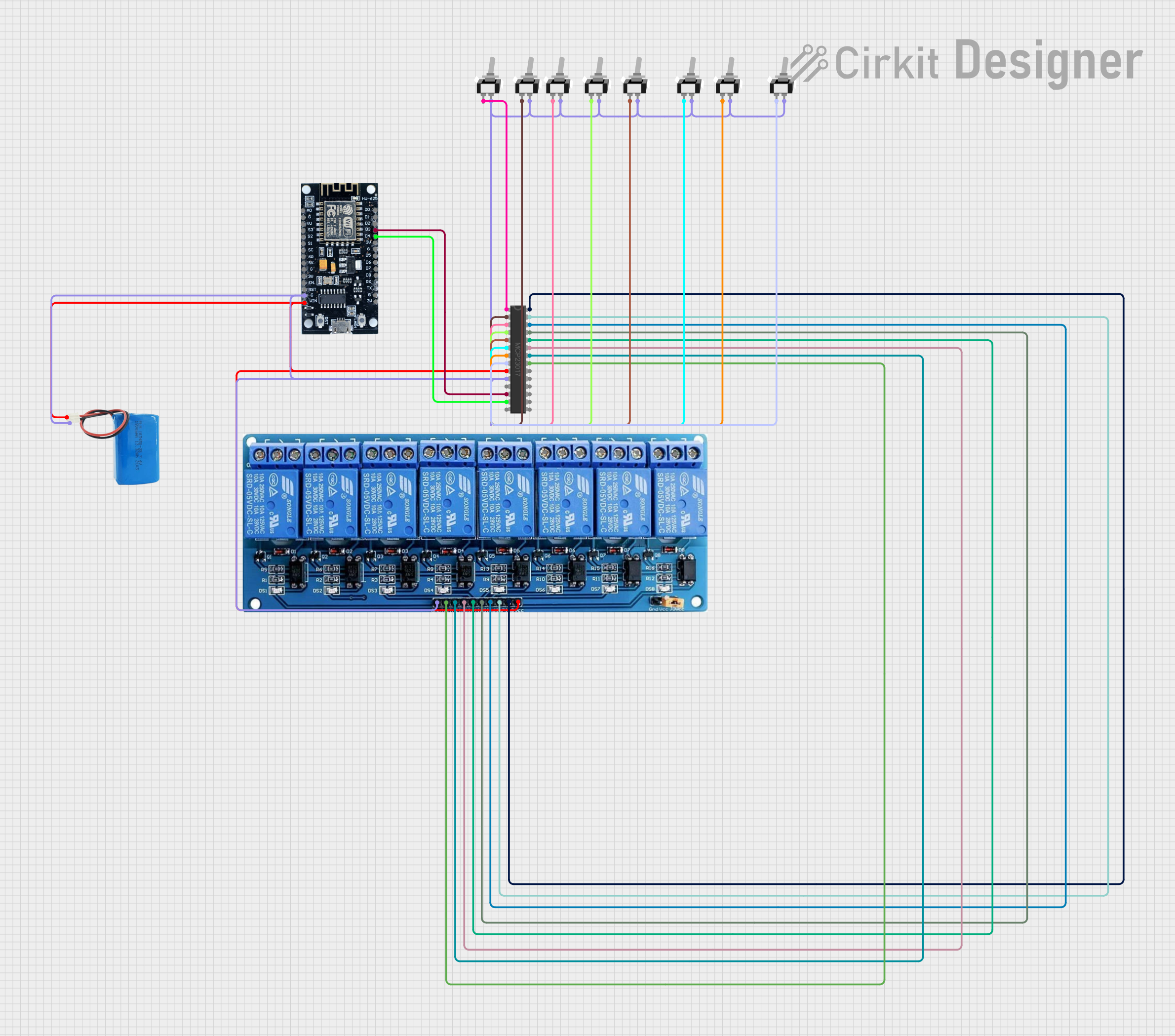
Wi-Fi Controlled Smart Relay Switch with ESP8266 and MCP23017

Circuit Documentation
Summary
The circuit in question is designed to control an 8-channel relay module using an MCP23017 I/O expander, which is interfaced with an ESP8266 microcontroller. The ESP8266 is responsible for connecting to a Wi-Fi network and communicating with an MQTT server to receive commands for controlling the relays. The MCP23017 expands the limited number of GPIOs available on the ESP8266 to control more devices, in this case, the relays. The relays are actuated by toggle switches connected to the MCP23017, and their state can be remotely monitored and controlled via MQTT. A 5V battery provides power to the circuit, and multiple single-pole single-throw (SPST) toggle switches are used to manually control the relays.
Component List
MCP23017 - I/O Expander
- Description: A 16-bit I/O expander with serial interface for expanding the number of I/Os available to a microcontroller.
- Pins: GPB0-GPB7, GPA0-GPA7, A0-A2, SDA, SCL, VSS, VDD, INTA, INTB, RESET, NC
5V 8-Channel Relay Module
- Description: A module with 8 relays that can be individually controlled to switch various loads on and off.
- Pins: GND, IN1-IN8, VCC, NC, C, NO
ESP8266 - Microcontroller
- Description: A Wi-Fi capable microcontroller with a limited number of GPIOs, suitable for IoT applications.
- Pins: 3V, G, D0-D8, A0, S0-SC, SK, EN, VIN, RST, VU
5V Battery
- Description: A power source providing 5V to power the circuit.
- Pins: Positive, Negative
Toggle Switch SPST (Multiple Instances)
- Description: A simple on/off switch to control the state of the relays manually.
- Pins: L1, COM
Wiring Details
MCP23017 - I/O Expander
- SDA connected to ESP8266 (D4)
- SCL connected to ESP8266 (D3)
- VSS connected to Ground (Common Ground Net)
- VDD connected to 5V Power (Common Power Net)
- GPB0-GPB7 connected to individual Toggle Switch SPST (L1)
- GPA0-GPA7 connected to 5V 8-Channel Relay Module (IN1-IN8)
5V 8-Channel Relay Module
- GND connected to Ground (Common Ground Net)
- VCC connected to 5V Power (Common Power Net)
- IN1-IN8 connected to MCP23017 (GPA0-GPA7)
ESP8266 - Microcontroller
- G connected to Ground (Common Ground Net)
- VIN connected to 5V Power (Common Power Net)
- D4 connected to MCP23017 (SDA)
- D3 connected to MCP23017 (SCL)
5V Battery
- Positive connected to 5V Power (Common Power Net)
- Negative connected to Ground (Common Ground Net)
Toggle Switch SPST (Multiple Instances)
- L1 connected to MCP23017 (GPB0-GPB7)
- COM connected to Ground (Common Ground Net)
Documented Code
#include <ESP8266WiFi.h>
#include <Adafruit_MCP23017.h>
#include <PubSubClient.h>

const char* ssid = "YOUR_WIFI_SSID";
const char* password = "YOUR_WIFI_PASSWORD";
const char* mqtt_server = "YOUR_MQTT_SERVER_ADDRESS";
const char* mqtt_user = "YOUR_MQTT_USER";
const char* mqtt_password = "YOUR_MQTT_PASSWORD";

WiFiClient espClient;
PubSubClient client(espClient);
Adafruit_MCP23017 mcp;

// Relay and switch pin mappings on MCP23017
const uint8_t relayPins[] = {0, 1, 2, 3, 4, 5, 6, 7};
const uint8_t switchPins[] = {8, 9, 10, 11, 12, 13, 14, 15};
bool relayState[8] = {false, false, false, false, false, false, false, false};

void setup() {
  Serial.begin(115200);
  setupWiFi();
  client.setServer(mqtt_server, 1883);
  client.setCallback(mqttCallback);

  // Initialize MCP23017
  mcp.begin(0);  // Default address 0x20

  // Set up relay pins as output
  for (uint8_t i = 0; i < 8; i++) {
    mcp.pinMode(relayPins[i], OUTPUT);
    mcp.digitalWrite(relayPins[i], LOW);  // Ensure relays are OFF initially
  }

  // Set up switch pins as input with pull-up
  for (uint8_t i = 0; i < 8; i++) {
    mcp.pinMode(switchPins[i], INPUT);
    mcp.pullUp(switchPins[i], HIGH);
  }
}

void loop() {
  if (!client.connected()) {
    reconnect();
  }
  client.loop();

  // Monitor switches and toggle corresponding relay
  for (uint8_t i = 0; i < 8; i++) {
    if (mcp.digitalRead(switchPins[i]) == LOW) {  // Switch is pressed
      toggleRelay(i);
      delay(200);  // Debounce delay
    }
  }
}

// Function to connect to WiFi
void setupWiFi() {
  delay(10);
  Serial.println();
  Serial.print("Connecting to ");
  Serial.println(ssid);

  WiFi.begin(ssid, password);

  while (WiFi.status() != WL_CONNECTED) {
    delay(500);
    Serial.print(".");
  }

  Serial.println("");
  Serial.println("WiFi connected");
}

// Function to handle MQTT reconnection
void reconnect() {
  while (!client.connected()) {
    Serial.print("Attempting MQTT connection...");
    if (client.connect("ESP8266Client", mqtt_user, mqtt_password)) {
      Serial.println("connected");
      // Subscribe to relay control topics
      for (uint8_t i = 0; i < 8; i++) {
        String topic = "living-room/relay" + String(i+1) + "/set";
        client.subscribe(topic.c_str());
      }
    } else {
      Serial.print("failed, rc=");
      Serial.print(client.state());
      Serial.println(" try again in 5 seconds");
      delay(5000);
    }
  }
}

// MQTT callback function to process messages
void mqttCallback(char* topic, byte* payload, unsigned int length) {
  String message;
  for (unsigned int i = 0; i < length; i++) {
    message += (char)payload[i];
  }

  // Control relays based on MQTT message
  for (uint8_t i = 0; i < 8; i++) {
    String relayTopic = "living-room/relay" + String(i+1) + "/set";
    if (String(topic) == relayTopic) {
      if (message == "ON") {
        setRelay(i, true);
      } else if (message == "OFF") {
        setRelay(i, false);
      }
    }
  }
}

// Toggle relay function
void toggleRelay(uint8_t relayNum) {
  relayState[relayNum] = !relayState[relayNum];
  mcp.digitalWrite(relayPins[relayNum], relayState[relayNum] ? HIGH : LOW);

  // Publish relay state to MQTT
  String stateTopic = "living-room/relay" + String(relayNum+1) + "/state";
  client.publish(stateTopic.c_str(), relayState[relayNum] ? "ON" : "OFF");
}

// Set relay state directly
void setRelay(uint8_t relayNum, bool state) {
  relayState[relayNum] = state;
  mcp.digitalWrite(relayPins[relayNum], state ? HIGH : LOW);

  // Publish relay state to MQTT
  String stateTopic = "living-room/relay" + String(relayNum+1) + "/state";
  client.publish(stateTopic.c_str(), state ? "ON" : "OFF");
}
This code is designed to run on the ESP8266 microcontroller. It initializes the Wi-Fi connection, connects to the MQTT server, and sets up the MCP23017 I/O expander. The ESP8266 monitors the state of the toggle switches through the MCP23017 and toggles the state of the corresponding relay. It also listens for MQTT messages to control the relays remotely and publishes the state of the relays back to the MQTT server.