
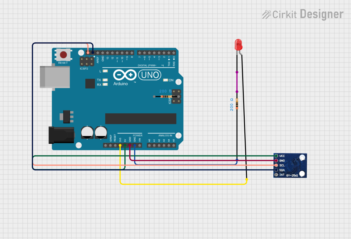
Circuit Documentation
Summary
This circuit consists of an Arduino UNO microcontroller, a TSL2561 Lux Sensor, a red LED, and two resistors. The Arduino UNO is used to read data from the TSL2561 Lux Sensor and control the LED. The resistors are used to limit the current through the LED.
Component List
Arduino UNO
- Description: A microcontroller board based on the ATmega328P.
- Pins: UNUSED, IOREF, Reset, 3.3V, 5V, GND, Vin, A0, A1, A2, A3, A4, A5, SCL, SDA, AREF, D13, D12, D11, D10, D9, D8, D7, D6, D5, D4, D3, D2, D1, D0
Resistor (200 Ohms)
- Description: A resistor with a resistance of 200 Ohms.
- Pins: pin1, pin2
TSL2561 Lux Sensor
- Description: A digital light sensor.
- Pins: INT, SDA, SCL, GND, VCC
Resistor (200 Ohms)
- Description: A resistor with a resistance of 200 Ohms.
- Pins: pin1, pin2
LED: Two Pin (red)
- Description: A red LED.
- Pins: cathode, anode
Wiring Details
Arduino UNO
- 3.3V: Connected to the anode of the red LED.
- 5V: Connected to the VCC pin of the TSL2561 Lux Sensor.
- GND: Connected to the GND pin of the TSL2561 Lux Sensor and pin1 of the resistor.
- SCL: Connected to the SCL pin of the TSL2561 Lux Sensor.
- SDA: Connected to the SDA pin of the TSL2561 Lux Sensor.
Resistor (200 Ohms)
- pin1: Connected to the GND pin of the Arduino UNO.
- pin2: Connected to the cathode of the red LED.
TSL2561 Lux Sensor
- VCC: Connected to the 5V pin of the Arduino UNO.
- GND: Connected to the GND pin of the Arduino UNO.
- SCL: Connected to the SCL pin of the Arduino UNO.
- SDA: Connected to the SDA pin of the Arduino UNO.
Resistor (200 Ohms)
- pin1: Connected to the GND pin of the Arduino UNO.
- pin2: Connected to the cathode of the red LED.
LED: Two Pin (red)
- anode: Connected to the 3.3V pin of the Arduino UNO.
- cathode: Connected to pin2 of the resistor.
Code Documentation
Arduino UNO Code
#include <SparkFunTSL2561.h>
#include <Wire.h>

// Create an SFE_TSL2561 object, here called "light":
SFE_TSL2561 light;

// Global variables:
boolean gain;     // Gain setting, 0 = X1, 1 = X16;
unsigned int ms;  // Integration ("shutter") time in milliseconds

void setup()
{
  // Initialize the Serial port:
  Serial.begin(9600);
  light.begin();

  // If gain = false (0), device is set to low gain (1X)
  // If gain = high (1), device is set to high gain (16X)
  gain = 1;

  // If time = 0, integration will be 13.7ms
  // If time = 1, integration will be 101ms
  // If time = 2, integration will be 402ms
  // If time = 3, use manual start / stop to perform your own integration
  unsigned char time = 2;

  // setTiming() will set the third parameter (ms) to the
  // requested integration time in ms (this will be useful later):
  light.setTiming(gain, time, ms);

  // To start taking measurements, power up the sensor:
  light.setPowerUp();
}

void loop()
{
  delay(ms);
  // Retrieve the data from the device:
  unsigned int visible, infrared;
  float vis, ir;

  if (light.getData(visible, infrared))
  {
    // getData() returned true, communication was successful
    Serial.print("Visible: ");
    Serial.print(visible);
    Serial.print(" Infrared: ");
    Serial.print(infrared);
    vis = float(visible);
    ir = float(infrared);
    Serial.print(" Ratio (Vis/IR): ");
    Serial.println(vis / ir);
  }
  else
  {
    // getData() returned false because of an I2C error, inform the user.
    byte error = light.getError();
    Serial.print("I2C error: ");
    Serial.println(error);
  }
}
This code initializes the TSL2561 Lux Sensor and reads the visible and infrared light levels. The data is then printed to the Serial Monitor. If there is an I2C error, it is also printed to the Serial Monitor.